Protocol analysis
R&S
®
RTP
679User Manual 1337.9952.02 ─ 12
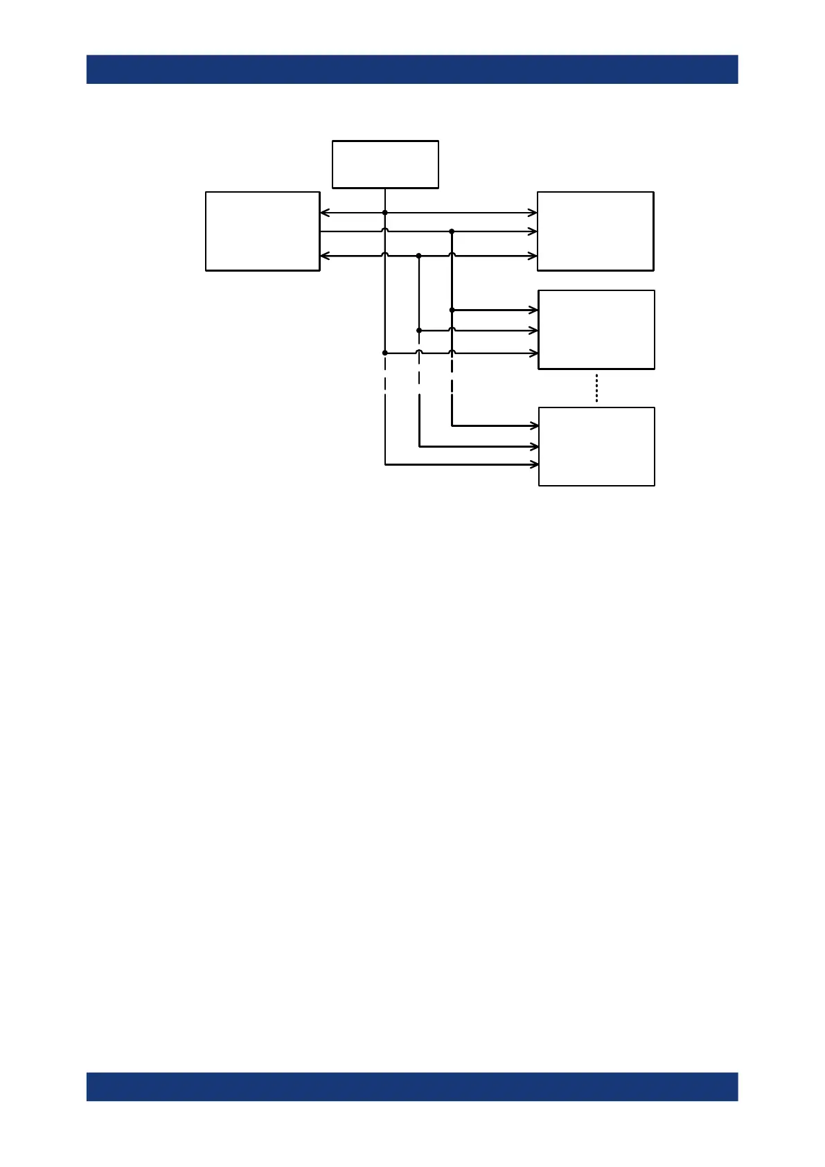
Master
(RFIC)
Slave 1
(FEM 1)
Slave 2
(FEM 2)
External VIO
supply
Slave n
(FEM n)
Figure 13-14: RFFE bus structure with external VIO supply
Command sequences
Protocol messages are called command sequences in RFFE. The standard defines
various command sequences to accomplish read and write access to slaves and to
non-active masters. Command sequences are initiated by the BOM master on the
SDATA line.
In general, a command sequence consists of:
●
Sequence start condition (SSC)
Two bits: 1 followed by 0 on SDATA while SCLK is at logic level zero.
●
Command frame
Consist of a 4-bit slave address field (SA), followed by 8 command payload bits
and a single parity bit.
●
Address and/or data frames, depending on the command sequence
A frame consists of 8 data bits or 8 register address bits, followed by a single parity
bit. The number of address and data frames varies depending on the command
sequence type.
●
Bus park cycle (BP)
A BP cycle is sent at the end of a command sequence, and when the device trans-
fers control of SDATA to another device.
Between the end of a command sequence and the beginning of a new command
sequence, the bus is in idle condition at least for 10 ns.
The bits are sent MSB first.
RFFE (option R&S
RTP-K40)

 Loading...


