Protocol analysis
R&S
®
RTP
894User Manual 1337.9952.02 ─ 12
For the basic trigger settings, proceed in the following way:
1. Press the [Protocol] key and select the "Shortcuts" tab.
2. Press "Setup trigger".
3. Tap the "Source" button and select the "Serial bus" trigger source.
4. Tap "Serial bus" and select the serial bus that is set to PCIe Gen 1/2.
5. Tap "Trigger Type PCI express" and select the trigger type to be used for PCIe Gen
1/2 protocol analysis.
6. Depending on the selected trigger type, more setup conditions can be specified.
For information on how to proceed with the configuration settings, see Chap-
ter 13.22.4.1, "PCIe trigger settings", on page 883.
13.22.5 PCIe Gen 1/2 decode results
When the configuration of the serial bus is complete, the signal can be decoded:
1. In the "Serial Bus" dialog > "Setup" tab, enable "Decode".
2. In the "Serial Bus" dialog > "Display" tab, select additional result display settings:
"Show table" and "Show binary".
3. If required, enable "Zoom coupling"
For a description of the display settings, see also Chapter 13.1.3, "Display",
on page 514.
The instrument captures and decodes the signal according to the standard definition
and the configuration settings.
The color-coding of the various protocol sections and errors simplifies the interpretation
of the visual display. The decode information condenses or expands, depending on the
horizontal scale. Various data formats are available to show the result values.
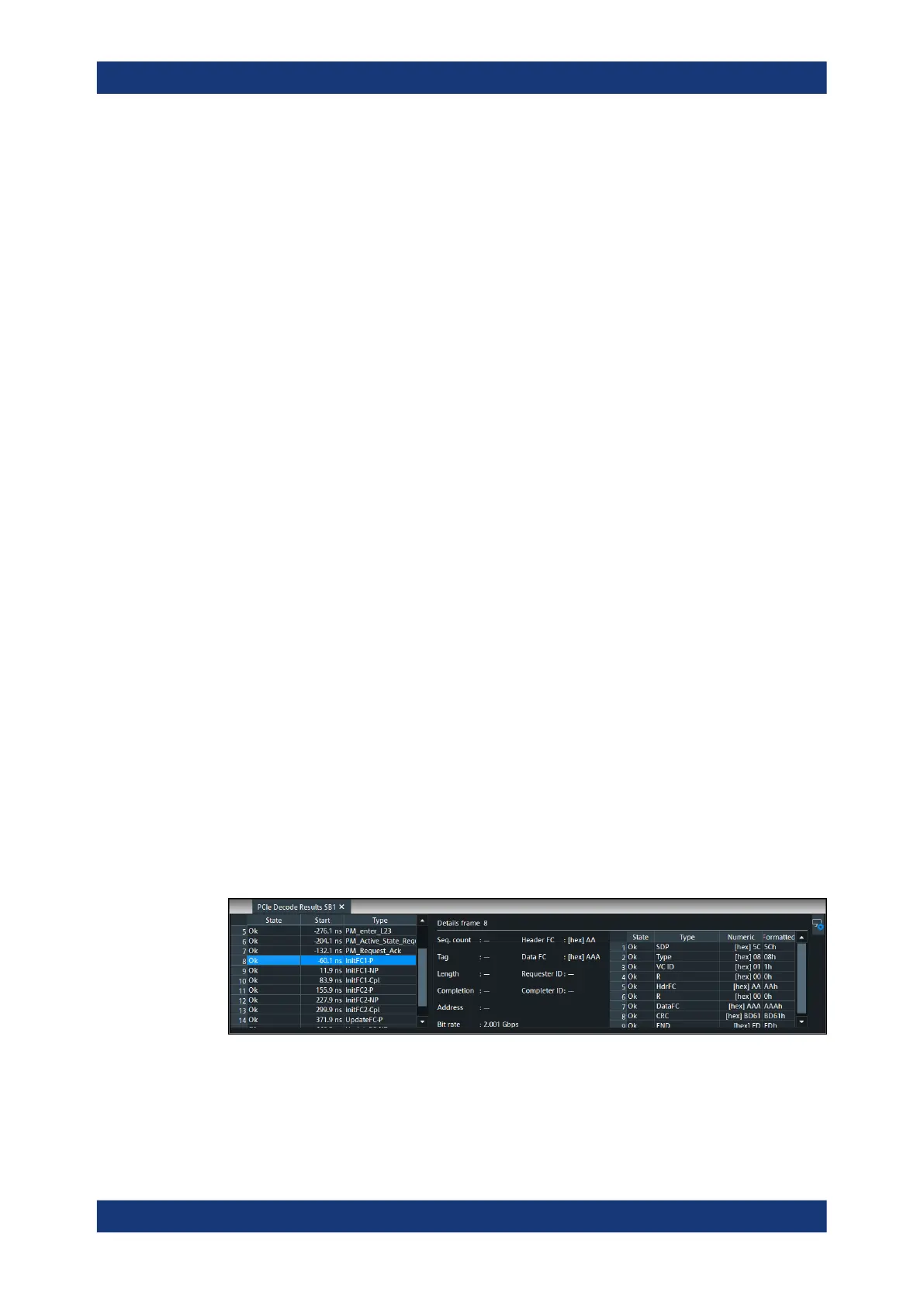
Decode results table
The results are shown in two tables:
●
"Decode results": contains information about all decoded frames
●
"Details frame": contains more detailed information about the selected frame in the
"Decode results" table.
PCIe (option R&S
RTP-K72/K73)