Acquisition and waveform setup
R&S
®
RTP
140User Manual 1337.9952.02 ─ 12
Differential active probes
Differential active probes are designed to measure signals that are referenced against
each other, and voltages that are not references to ground, for example twisted-pair
signal lines. The R&S RT-ZD probes are differential probes with high input impedance,
they can be used to measure voltages between any two test points.
Compared with two-channel measurement setup with single-ended probes, the mea-
surement with differential probes is symmetric due to the same amplification and cable
length on both paths. It is also immune to interference and noise and occupies only
one input channel.
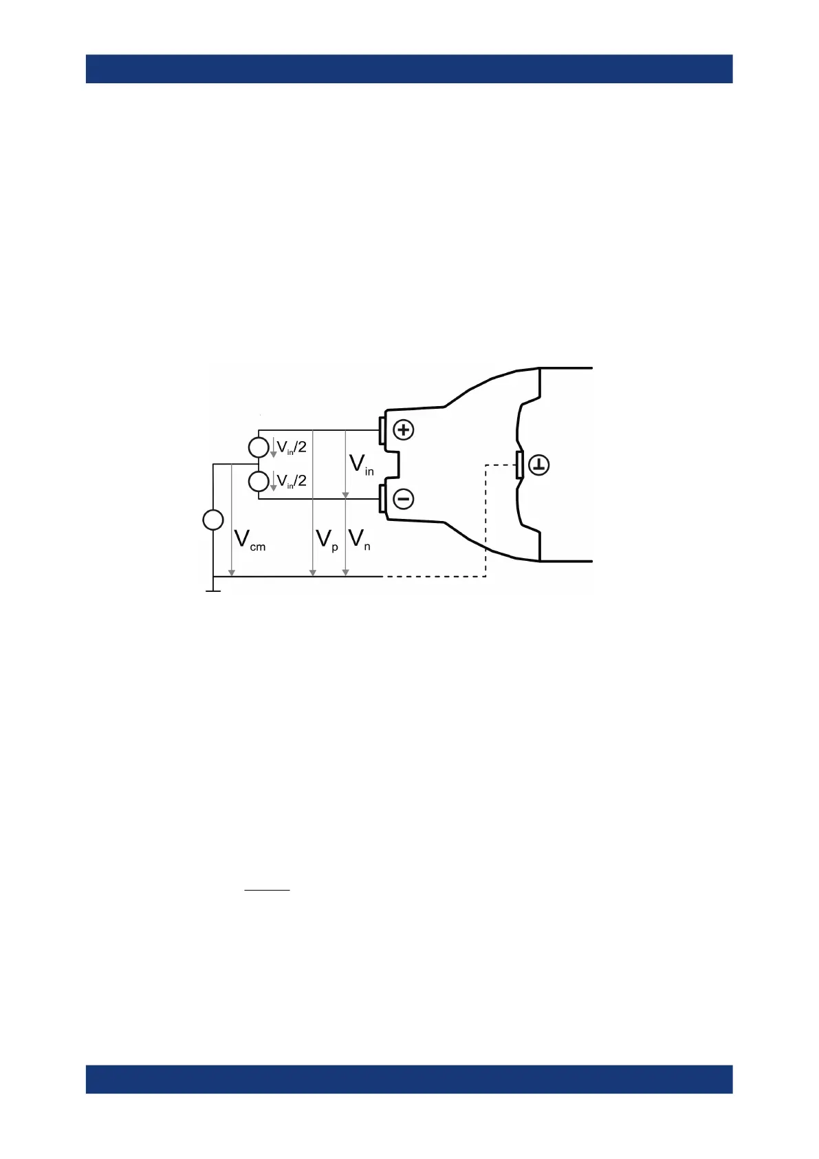
A differential probe has three sockets: the positive signal socket (+), the negative sig-
nal socket (-), and the ground socket.
Multiple input voltages can be defined for a differential probe:
●
Differential mode input voltage (V
in
, V
dm
)
Voltage between the positive and negative signal sockets
●
Positive single-ended input voltage (V
p
)
Voltage between the positive signal socket and the ground socket
●
Negative single-ended input voltage (V
n
)
Voltage between the negative signal socket and the ground socket
●
Common mode input voltage (V
cm
)
Mean voltage of positive and negative signal sockets referred to the ground socket,
respectively
Two of these voltages are independent values, the other two can be calculated:
R&S RT-ZD probes detect only differential input voltages and provide it to the oscillo-
scope. Common mode signals are suppressed by the probe. This characteristic is
described by the common mode rejection ratio (CMRR):
Basics

 Loading...


