H1: Manual and handwheel travel
3.7 DRF offset
Extended Functions
182 Function Manual, 03/2013, 6FC5397-1BP40-3BA1
$[LVQ
$[LV
$[LV
+0,,6'5)VHOHFWHG
$FWLYDWH'5)
LQWHUIDFHVLJQDO
$XWRPDWLFDFWLYHPRGH
+DQGZKHHO
$FWLYHPDFKLQH
IXQFWLRQLQWHUIDFH
VLJQDO
+DQGZKHHOSXOVHV
SHUORFNLQJSRVLWLRQ
6HOHFWHGLQFUHPHQW
VL]H
'5)DFWLYH
[
[
0RGLI\LQFUHPHQWDOO\
5HDG
,6
RSHUDWRU
3/&XVHU
SURJUDP
1&
SDUWSURJUDP
+//
'5)RIIVHW
5HDG
5HDG
'HOHWH
,1& 0'01B-2*B,1&5B6,=(B7$%
,1&YDU 6'01B-2*B9$5B,1&5B6,=(
0'01B+$1':+B,03B3(5B/$7&+
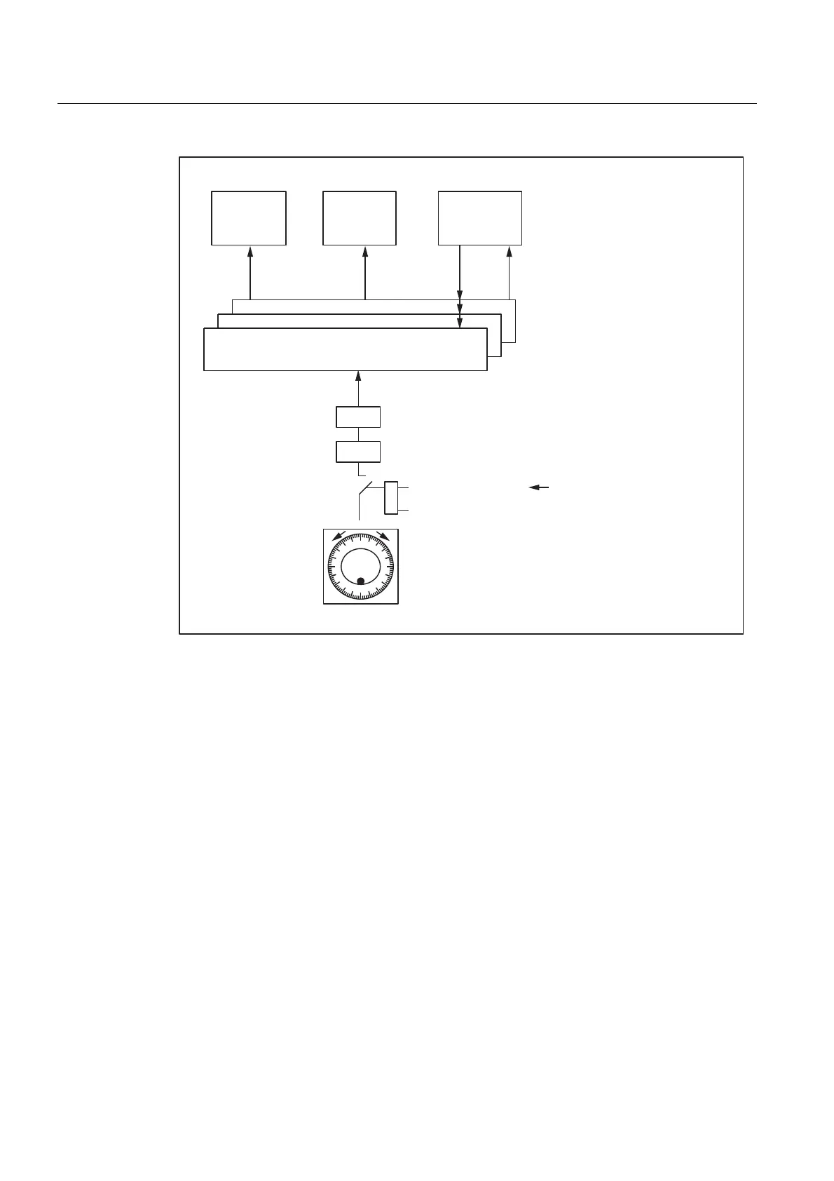
Figure 3-5 Control of DRF offset
Display
The axis actual-position display (ACTUAL POSITION) does not change while an axis is
being traversed with the handwheel via DRF. The current axis DRF offset can be displayed
in the DRF window.
Reference point approach
In phase 1 of the machine-axis reference point approach, the DRF offset for the
corresponding geometry or auxiliary axis is deleted.
During the machine-axis reference point approach, a DRF offset for the corresponding
geometry or auxiliary axis cannot be performed simultaneously.
Reset response
PowerOn-Reset: The DRF offset is deleted.

 Loading...


