M1: Kinematic transformation
6.10 Examples
Extended Functions
Function Manual, 03/2013, 6FC5397-1BP40-3BA1
423
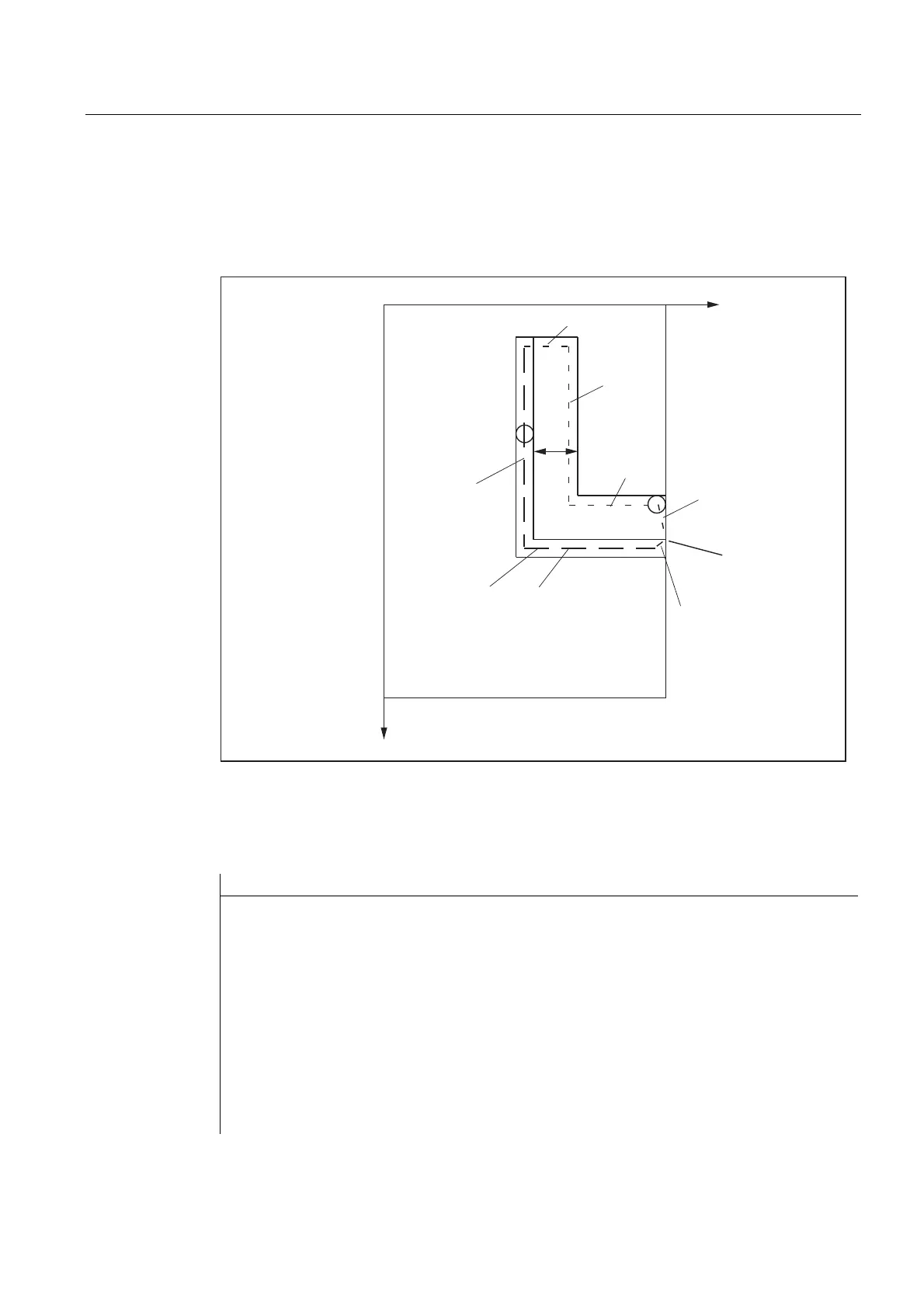
Tool radius
The tool radius is automatically taken into account with respect to the groove side wall (see
simplified figure). The full functionality of the plane tool radius compensation is available
(steady transition at outer and inner corners as well as solution of bottleneck problems).
1
1
1
3URJUDPPHGSDWK
3DWK,,
1
1
3DWK,
1
1
2))1
<
=
Figure 6-30 Groove with groove wall offset, cylinder coordinates
Example program that which guides the tool after transformation selection on path I via path
II back to the starting position
Program code Comment
N1 SPOS=0; ; Transfer the spindle to rotary axis
operation
N5 G0 X25 Y0 Z105 CC=200 F5000 G64 ; Positioning of the machine above
groove center
N10 TRACYL(40.) ; Transformation selection with
reference diameter: 40 mm
N20 G19 G90 ; Machining plane is cylinder surface
N30 T1 D1 ; Tool selection, can also be before
TRACY (..)
N30 T1 D1 ; Infeed tool to groove base
N50 OFFN=12 ; Determine groove wall distance; it
does need not to be in its own line

 Loading...


