M5: Measurement
7.5 Setting zeros, workpiece measuring and tool measuring
Extended Functions
454 Function Manual, 03/2013, 6FC5397-1BP40-3BA1
Measuring points
A maximum of four measuring points are available for all channel axes for measurement:
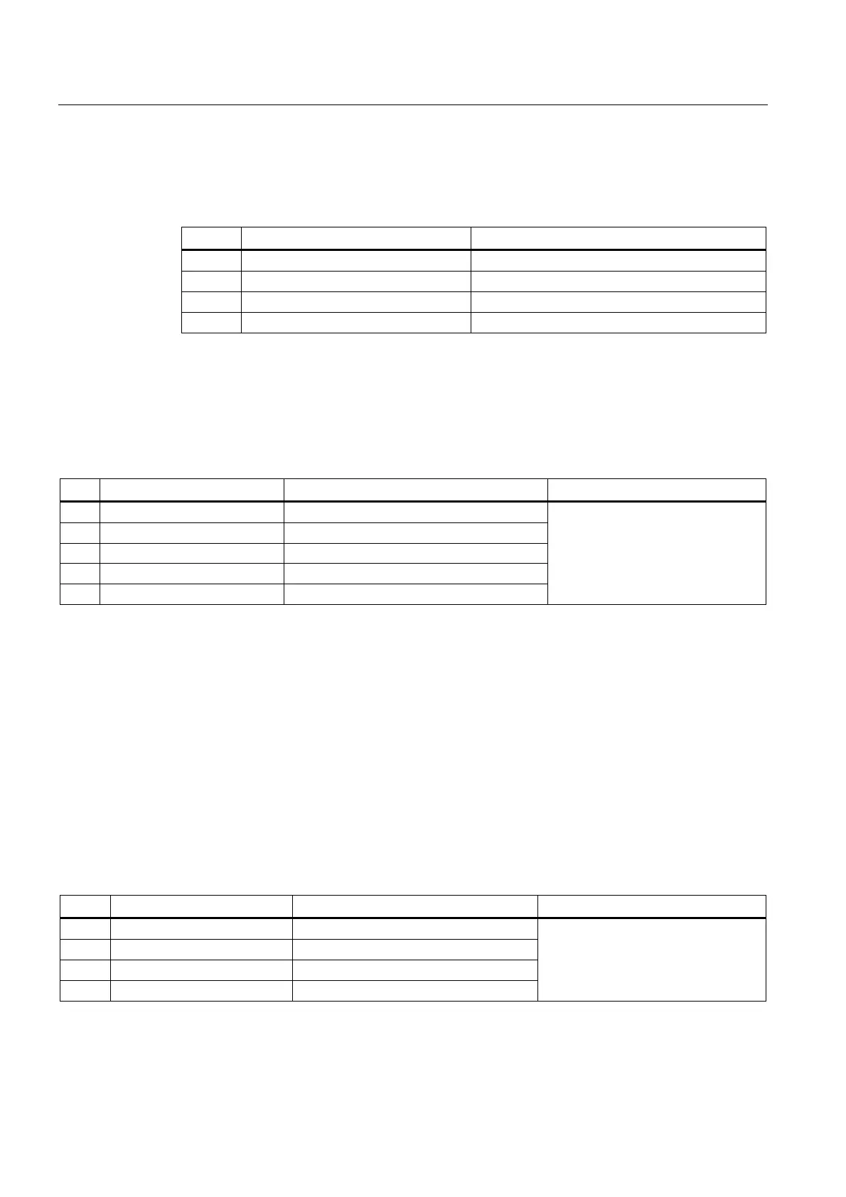
Type Input variable Meaning
REAL $AA_MEAS_POINT1[axis] 1. Measuring point for all channel axes
REAL $AA_MEAS_POINT2[axis] 2. Measuring point for all channel axes
REAL $AA_MEAS_POINT3[axis] 3. Measuring point for all channel axes
REAL $AA_MEAS_POINT4[axis] 4. Measuring point for all channel axes
The measured points are normally available as actual values (= setpoint values) in WCS. A
measuring point is denoted as valid as soon as an axis value is described for it. Each
individual measuring point can be written or picked up.
A few measuring types also support measuring points lying in a different coordinates system
(BCS, MCS). The entry in which the coordinates system of the corresponding measuring
point was measured can be done via the following variables:
Type Input variable Meaning Values
INT $AA_MEAS_P1_COORD Coordinate system of 1st measuring point
INT $AA_MEAS_P2_COORD Coordinate system of 2nd measuring point
INT $AA_MEAS_P3_COORD Coordinate system of 3rd measuring point
INT $AA_MEAS_P4_COORD Coordinate system of 4th measuring point
INT $AA_MEAS_SET_COORD Coordinate system of setpoint
0: WCS is the standard setting
1: BCS
2: MCS
3: ENS
4: WCS_REL
5: ENS_REL
Actual values
The measuring points can be described for all the axes having the current axis actual values.
The positions are picked up with reference to the selected coordinates system. The positions
are attached in WCS if no coordinates system is specified. The following variable is used for
this purpose:
$AC_MEAS_LATCH[0..3]
The index varies from 0 to 3, corresponding to the 1st to 4th measuring point. Assigning the
value zero to the variable has the effect that all axis actual values of the corresponding
measuring point become invalid. Assigning the value 1 picks up all the axis actual values in
the corresponding measuring point. The variable is a write-only variable.
Individual axis actual values of a measuring point can be described with the following
variables:
Type System variable Meaning Values
REAL $AA_MEAS_P1_VALID[ax] 1. Pick up the measuring point of an axis
REAL $AA_MEAS_P2_VALID[ax] 2. Pick up the measuring point of an axis
REAL $AA_MEAS_P3_VALID[ax] 3. Pick up the measuring point of an axis
REAL $AA_MEAS_P4_VALID[ax] 4. Pick up the measuring point of an axis
0: The measuring point of the axis is
invalid
1: The measuring point of the axis is
determined
The variables $AC_MEAS_LATCH[0..3] and $AA_MEAS_P[1..4]_VALID can be used
interactively. Allowance is made accordingly for the facing axis with diameter programming.

 Loading...


