DISPLAY AND CONTROL ELEMENTS 4
MHL360 E 4.39
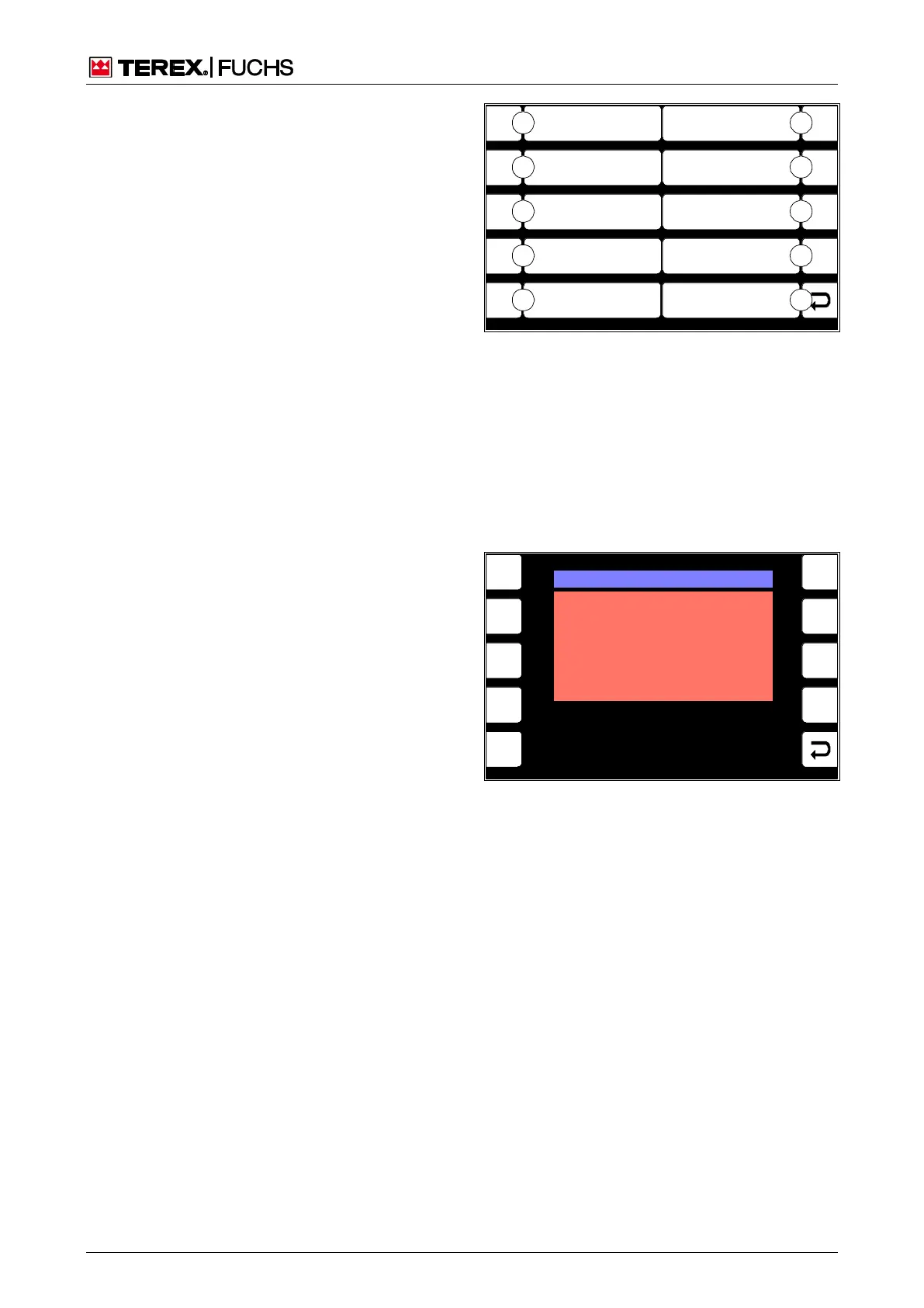
4.5.13 Diagnostics menu
The Diagnostics menu offers additional dis-
play screens for displaying operating states
and machine settings.
Call-up
►
Main control display > Main menu > Diag-
nostics menu
Structure
The Diagnostics menu is structured as a two-
column table.
Operating note
►
Briefly press side function key next to the
desired button (70/0-9).
or multifunction button
►
Navigate focus to button (70/0-9).
► Briefly press button.
4.5.13.1 CANopen diagnostics
This display screen indicates the status of the
components connected on the CANopen bus.
Call-up
►
Main control display > Main menu > Diag-
nostics menu > CANopen diagnostics
F1
F2
F3
F4
F6
F7
F8
F9
F5
BSB51160
ESC
Lamp Test
Diagnostics Lubrication
LE - Diagnostics
3
2
1
0
4
8
7
6
5
9 CANopen - Diagnostics
OPERATING HOURS
ECU - Diagnostics
Diagnostics Magnet System
Fig. 70 Diagnostics menu
0 Back
1 ECU diagnostics
2 Not assigned
3 Operating hours
4 CANopen - diagnostics
5 LE - diagnostics
6 Grease lubrication system diagnostics
7 Magnet system diagnostics
8 Not assigned
9 Lamp Test
F1
F2
F3
F4
F6
F7
F8
F9
F5
BSB50623
CAN1 I/O Extension BUS DIGNOSTIS
NO COMMUNICATION
TO
MAIN CONTROLLER UNIT
Fig. 71 CANopen diagnostics