4 DISPLAY AND CONTROL ELEMENTS
4.44 MHL360 E
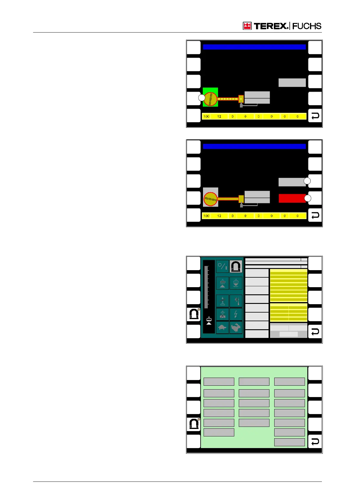
Setup of manual operation
The display screen for manual mode appears
when the diesel engine is switched off (Fig.
80). If the diesel engine is started, the screen
changes to automatic mode. The pump then
runs according to the parameters and cycles
displayed.
Operating note
The lubricating pump can be manually
switched. It then runs without interruption.
►
Briefly press side function (80/1) key.
or multifunction button
►
Navigate focus to button (80/1).
►
Briefly press button.
Resetting error and status messages
Displayed error and status messages can only
be reset in manual mode. If the error mes-
sage is not reset, automatic lubrication cannot
take place.
Operating note
►
Briefly press side function key (81/1 or 2).
or multifunction button
►
Navigate the focus to the button (81/1 or
2).
►
Briefly press button.
h Chapter 7.5.3.2 Lubrication when lubricat-
ing pump is faulty
4.5.13.7 Magnet system diagnostics
These display screens provide service per-
sonnel with detailed information on the mag-
net system state.
Call-up
►
Main control display > Main menu > Diag-
nostics menu > Magnet system diagnostics
F3
F4
F6
F7
F8
F9
F5
F1
F2
BSB50885
Uppercarriage grease lubrication system
Status change
Detected
Status
Piston detector
HIGH = GR EEN
LOW = G RAY
1
Pump
Fig. 80 Manual mode
F3
F4
F6
F7
F8
F9
F5
F1
F2
BSB50886
Uppercarriage grease lubrication system
Pump
Status
Piston detector
HIGH = GR EEN
LOW = G RAY
ERROR
Status change
Detected
1
2
Fig. 81 Pump stationery with error message
1 ERROR
2 Status change detected
MENUE
2
BSB51118
GEM A ER RO R
UCE Cl ock
Ov erload ( OC)
Ov ervoltage (OV)
Ov ertem perature
UCE Top Left
UCE Bottom Left
UCE Top Right
UCE Bottom Right
Outpt Limtatn Actv
Trq Limitati on Actv
Ov ertem perature
ISO
100
90
80
70
60
50
40
30
20
10
0 %
CAN
KWG-PLC STATUS
MCU-PLC STATUS
0
0
MAGNET VOLTAGE
MAGNET CURRENT
MAGNET POWER
SPEED
ELECTR. TEMP.
TORQUE
ISO VALUE
UZK1
0 V
0 kOhm
0 Nm
0 °C
0 1/min
0 W
0 A
0 V
WARNINGS
Regulator
Outpt Limtatn Actv
Trq Limitation Actv
Overtemperature
OC
Magnetic Plate
ISO
Clock Missing
ERRORS
LIMIT VALUES
MAGNET POWER
0 W
TORQUE
0 Nm
MAGNET VOLTAGE
0 V
UCE Top Right
UCE Bottom Right
Over Current (OC)
Overtemperature
UCE Top Left
UCE Bottom Left
UCE Clock
Overvoltage (OV)
Fig. 82 Magnet system data, menu 1 (for service
personnel)
BSB51120
HISTORY-DATA
TYPE KEY
0
SOFTWARE V ERSION
0
SERIAL NUMBER
0
OPERATING HOURS
0 :0 [h:m]
Start Up Count
0 [n]
Over Temp Er ror Count
0 [n]
Idle [%]
0
ISO Selftest Cou nt
0 [n]
Over Temp Warn ing Count
0 [n]
Magne t ON [%]
0
Over Load OC Count
0 [n]
ISO Warning C ount
0 [n]
Output Power Limitation [%]
0
Over Voltage OV Count
0 [n]
DVR Warn ing Count
0 [n]
Torque Limitat ion [%]
0
OC Warning C ount
0 [n]
Magne t Plate Warning C ount
0 [n]
READ
DATA
MENUE
1
Fig. 83 Magnet system data, menu 2 (for service
personnel)