OPERATION 5
MHL360 E 5.1
5.1 n Safety
5.1.1 Protection function of the cab
The structural design of the cab provides a
high degree of safety. It cannot however
guarantee complete protection.
The operating personnel are responsible for
ensuring that they buckle themselves in, that
the SWL is adhered to, that work only takes
place on a solid and even surface, and the
loading machine moves in such a way that no
hazardous situations arise.
Additional safety measures are necessary if
material to be loaded could fall in the area of
the cab or if, due to slopes in the terrain, a
toppling loading machine can roll over the
cab.
Damage may impair the structural safety of the
cab. Damaged cab parts may only be replaced
by original parts from the machine manufacturer.
Damage to the steel structure (cracks, buckles,
distortion) must not be repaired. The cab should
be replaced with an original cab from the ma-
chine manufacturer.
5.1.2 Armrest switch
If the left armrest is flipped up, travel and work
functions are disabled. This reduces the dan-
ger of control elements being actuated inad-
vertently. If work operation is interrupted, flip
up the left armrest if possible.
Always flip up the left armrest:
Before standing up from the operator's seat
Before leaving the cab
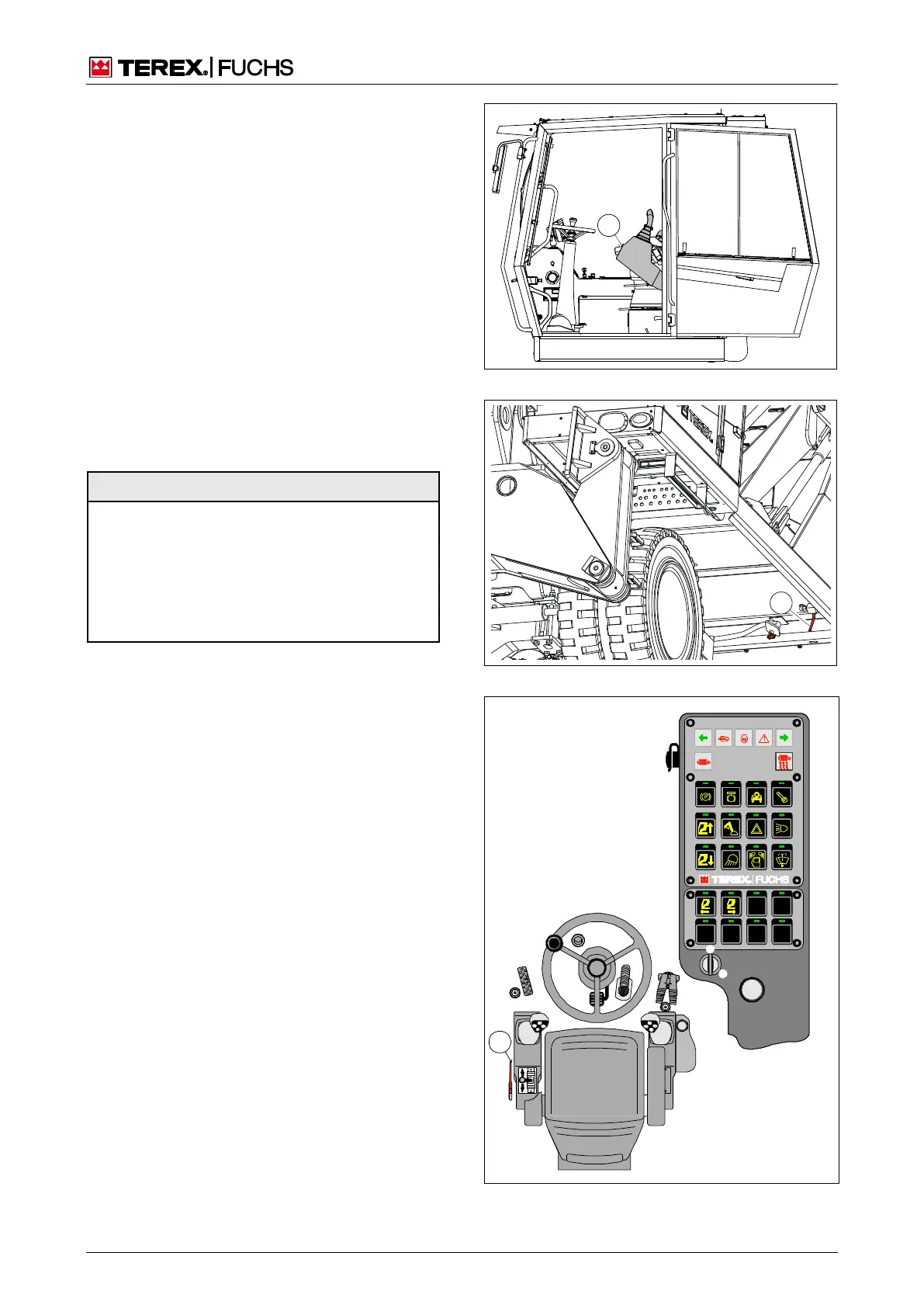
5.1.3 Emergency lowering of cab
If the control for the adjustable cab fails due to
a malfunction in the diesel engine or because
of some other fault, it can be lowered with the
emergency cab lowering function. Depending
on the situation, emergency lowering can be
carried out from inside using the ball valve,
(91/1) or from outside with the ball valve
(90/1).
In order to adjust the cab again after lowering,
the ball valves (91/1) and (90/1) must be re-
turned to the shut-off position.
Fig. 89 Upward folding left armrest
Fig. 90 External emergency lowering
Fig. 91 Internal emergency lowering
Emerge
ncy
lowerin
g of
cab
90