TECHNICAL DATA 3
MHL360 E 3.1
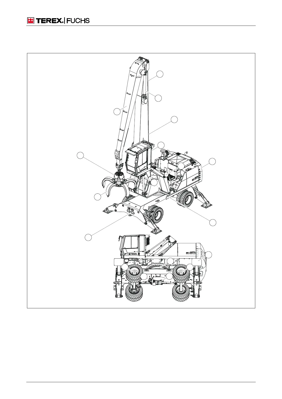
3 Technical data
3.1 General structure
1 0
3
4
1
6
2
5
7
8
1 3
9
1 4
11
C
D
1 2
B
A
BSB50891
Fig. 7 General structure
Adjustable cab
Cab lift frame
Counterweight
Slewing ring with swing gear and
swing brake
0 4-point outrigger
1 Front axle (steering axle) with drum
brakes (service brake)
2 Rear axle (oscillating axle) with
drum brakes (service brake)
3 Disk brake (parking brake)
4 Variable speed hydraulic motor with
two-stage manual transmission
Lift cylinder
Boom
Dipperstick cylinder
Dipperstick
Working equipment
Cactus grab