CARE AND MAINTENANCE 7
MHL360 E 7.25
7.5.1 Automatic central lubrication sys-
tem for uppercarriage, loading
equipment and work attachment
mounting
Various lubricating points are connected to
the automatic, time-controlled central lubrica-
tion system.
h Chapter 7.5 Overview of lubricating points
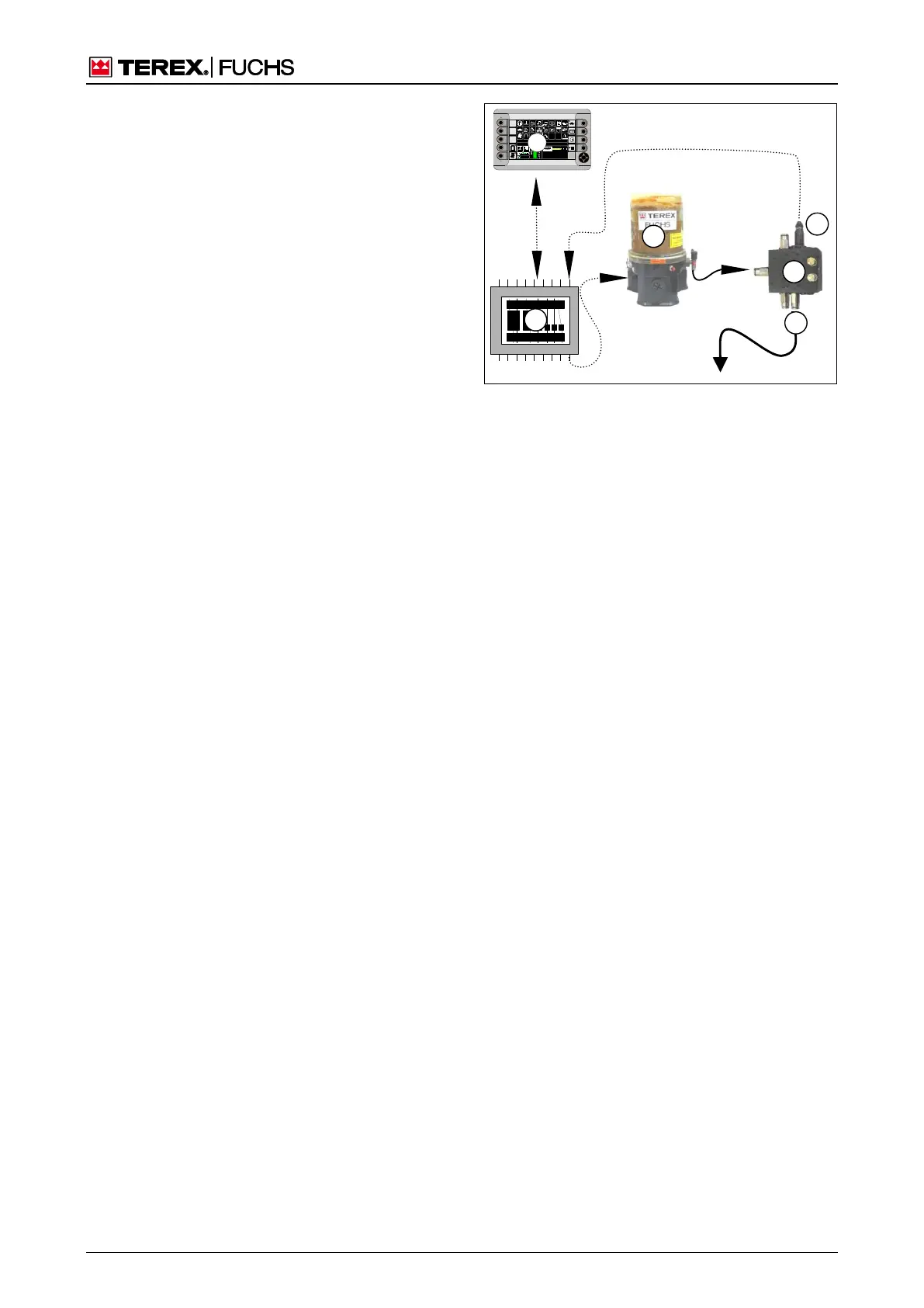
Operating principle
The lubricating pump (273/1), which consists
of a grease reservoir, agitator and pump,
supplies the lubricating points with lubrication
grease via several distributors (273/2).
The main control (273/5) switches the pump
on and off automatically. The pre-set grease
lubrication pause time is 28 minutes. It can
only be changed by a service engineer in the
service menu (273/6). An additional lubrication
cycle can be activated if necessary.
h Chapter 7.5.3.1 Triggering an additional
lubrication pulse
The distributor of lubricants (273/2) transports
the lubrication grease to other distributors and
directly to the lubricating points (273/3) via
pistons. A piston detector (273/4) is connect-
ed to one of the distributors. It detects the
piston movement in the distributor. If no piston
movement is detected within a number of lu-
brication cycles, it is assumed that there is a
fault. An error message appears in the main
control display on the multifunction monitor
(273/6). Automatic lubrication stops.
h Chapter 7.5.3.2 Lubrication when lubricat-
ing pump is faulty
Diagnostics for grease lubrication system
(optional)
The diagnostics function displays the operat-
ing modes, parameters and current status for
central grease lubrication. Pending error mes-
sages can be reset.
h Chapter 4.5.13.6 Grease lubrication sys-
tem diagnostics
F
09:43 11.03.2011
MHLXXX / XXXX
1800 UPM
0 5 10 15 20 25
95°C 75°C
0 ½ 1
9 %
120 0
1
2
4
5
3
6
BSB60015
Fig. 273 Operating principle of central lubrication
system
1 Lubricating pump
2 Distributor
3 Outgoing lubricating pipe to another distributor or a
lubricating point
4 Piston detector
5 Main control
6 Multifunction display