DISPLAY AND CONTROL ELEMENTS 4
MHL360 E 4.15
4.2.10 Multifunction display
4.2.10.1 Structure
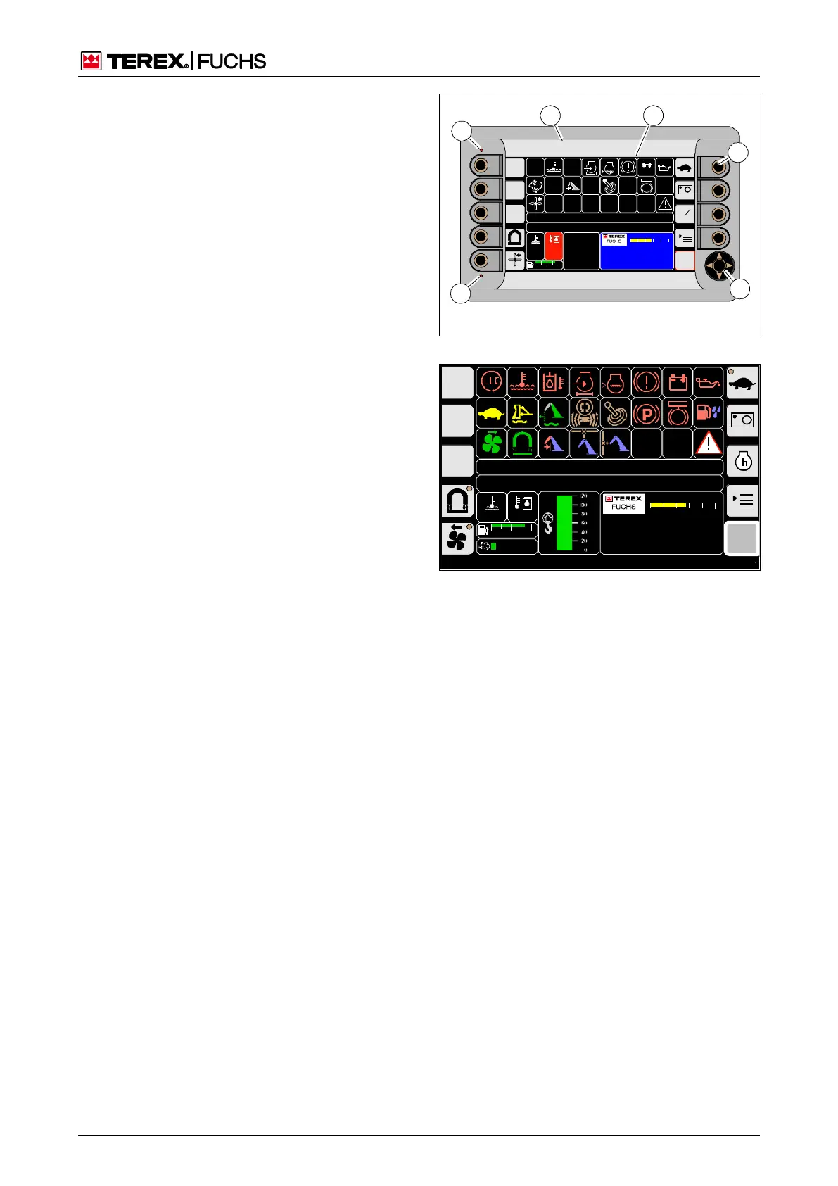
The multifunction display (Fig. 31) consists of:
Housing (31/1), secured via an adjustable
support arm on the user console.
Color display (31/2)
Function keys (31/3) with background light-
ing and soft key function
4-way rocker switch (31/4), with arrow keys
in the actuation direction and central button
with circular symbol
LED (31/5) for the visualization of process-
es, for example, flashing when the machine
control unit is booting up
Light sensor (31/6)
4.2.10.2 Display screens
Various display screens for communication
between operating personnel and machine
control unit appear on the screen. Some of
the individual display screens appear auto-
matically or can be opened by the operating
personnel via the menu structure. Special
display screens are available for authorized
service personnel which appear only after an
access code is entered.
4.2.10.3 Operating states
Normal mode
If the ignition is switched on after a long peri-
od of time, the display electronics need a few
seconds to ramp up. The functionalities of the
display are not available during this time.
Once the display control unit is fully booted
up, the main control display appears on the
screen (Fig. 32).
Standby mode
After the ignition is turned off, the display
electronics switch to standby mode for 10
minutes. When the ignition is switched on, the
functionalities are immediately available dur-
ing this time. After 10 min, the display switch-
es off automatically.
BSB50537
11
95
C
100
C
00 :00
h
F
0 ½ 1
09 :43 11 .03 .2 011
M HL XXX / X XXX
18 00 UPM
0 5 10 15 20 25
6
4
3
2
5
1
Fig. 31 Multifunction display
BSB50553
F
09:43 11.03.2011
MHLXXX / XXXX
1800 UPM
0 5 10 15 20 25
120 0
ARBEITSHYDRAU LIK IST GESPERRT
FEHLERMELDUNG
95°C 75°C
0 ½ 1
9 %
BSB50557
Fig. 32 Main control display