DISPLAY AND CONTROL ELEMENTS 4
MHL360 E 4.33
4.5.7 Magnet system (optional)
The magnet system is used for handling fer-
rous materials. It is switched on or off using
the main control display. Magnetiza-
tion/demagnetization is performed using a
button on the left-hand four-way control lever.
For operation purposes, the main control dis-
play offers the option of a normal magnet sys-
tem display or a comfort magnet system dis-
play. Which of the two displays appears de-
pends on what is selected in the display set-
tings menu. The isolation guard (ISO guard)
continually monitors the isolation resistance of
the entire magnet system (generator, elec-
tronics, cabling, magnetic plate).
h Chapter 4.5.11 Display settings
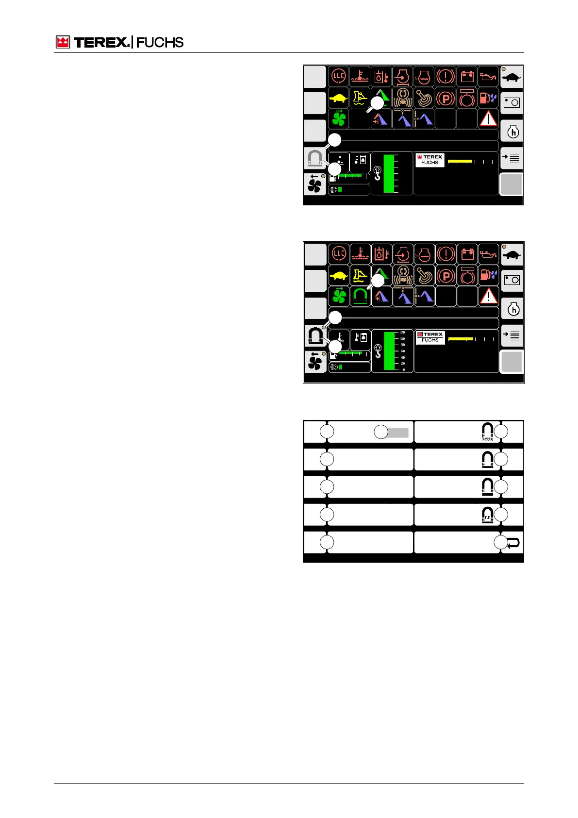
4.5.7.1 Normal magnet system display
with operating mode selection
menu
Call-up
►
Main control display
Structure
The button for the magnet system is marked
with the symbol (59/1). When the ignition is
switched on, the symbol is gray; once the die-
sel engine starts, it is black. When the diesel
engine is running and button (59/1) is activat-
ed, a symbolized LED (59/2) appears. When
the magnet system is ready to operate, the
indicator (59/3) then appears. Its color indi-
cates the status of the magnetic plate.
Green: not magnetized
Yellow: magnetized
Orange: magnetized, generator speed too
low.
Blue: ISO guard function test is running
The appearance of the symbol in the indicator
(59/3) shows the current operating mode. To
change this, activate button (59/1) until the
magnet system operating mode selection
menu appears (Fig. 60). This menu allows
you to select an operating mode and shows
the current isolation resistance measurement
(60/10). If required, you can use button (60/9)
to initiate an ISO guard function test manually.
If this fails, an error message will appear.
Operating note
h Chapter 5.20.1 Magnet system (optional)
F
09:43 11.03.2011
MHLXXX / XXXX / LE XXX
1800 UPM
0 5 1 0 1 5 2 0 2 5
120 0
ARBEITSHYDRAULIK IST GESPERRT
FEHLERMELDUNG
95°C 75°C
0 ½ 1
9 %
120
100
8 0
6 0
4 0
2 0
0
BSB51129
2
3
1
BSB51129
3
1
Fig. 58 Normal magnet system display when igni-
tion is switched on
BSB50553
F
09:43 11.03.2011
MHLXXX / XXXX
1800 UPM
0 5 10 15 20 25
120 0
ARBEITSHYDRAU LIK IST GESPERRT
FEHLERMELDUNG
95°C 75°C
0 ½ 1
9 %
BSB50558
2
3
1
Fig. 59 Normal magnet system display and mag-
net system ready to operate
F 1
F 2
F 3
F 4
F 6
F 7
F 8
F 9
F 5
C hips
Middle Parts
Large Parts
Tap Mode
ESC
Test Iso-M o nit. x kO h m
BSB51122
3
2
1
0
4
8
7
6
5
9
1 0
Fig. 60 Magnet system operating mode selection
menu
0 Back
1 Jog mode
2 Large parts
3 Medium parts
4 Chips
5-8 Not assigned
9 ISO guard function test
10 Current isolation resistance measured value
Magnet
system
(option