4 DISPLAY AND CONTROL ELEMENTS
4.2 MHL360 E
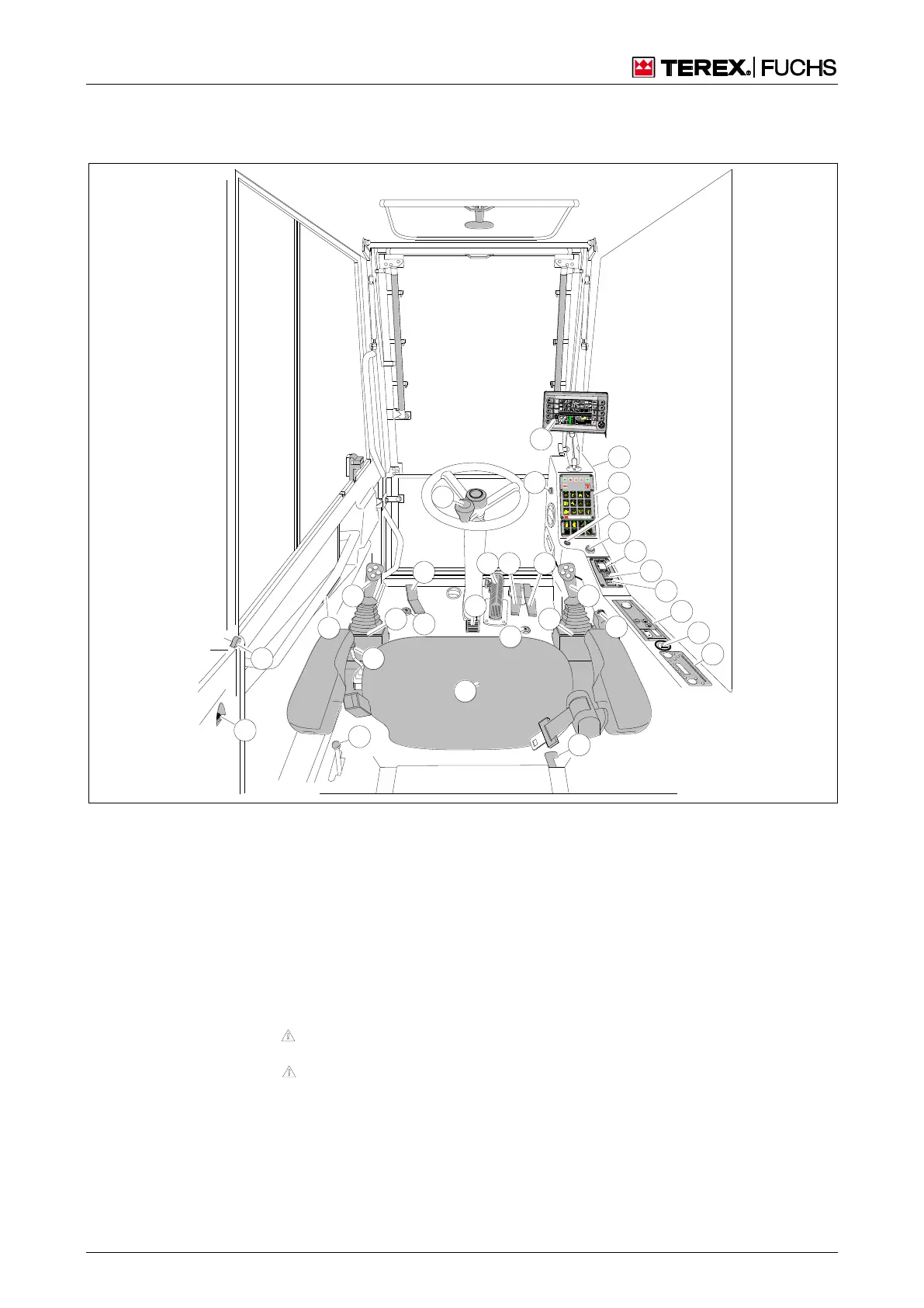
4.1 Display and control elements in the cab
4.1.1 Cab overview
BSB50894
1 2
5
2 5
1
7
9 1 0
11
1 3
1 5
6
3
1 7
1 8
2 7
2 6
3 1
3 4
2 9
3 2
3 3
2 8
1 4
8
3 5
3 6
3 7
4
2
1 9
2 0
1 2
1 6
Fig. 17 Cab overview
1 Emergency lowering of cab
2
Lever to extend/retract 4-point outrigger
Four-way control lever, left
Upward folding armrest with switch (disable travel
and work functions)
Foot switch for swing brake (optional)
Pedal for extending/retracting tilting cylinder (option-
al)
Steering wheel
Steering column adjustment (inclination angle)
Service brake pedal, lockable
0 Forward accelerator pedal (n Note alignment of
uppercarriage/undercarriage!)
1 Reverse accelerator pedal (n Note alignment of
uppercarriage/undercarriage!)
2 Seat
3 Four-way control lever, right
4 Fixed armrest
5 Multifunction button
6 Temperature control for lunchbox/bottle holder
7 12 V socket (optional)
18 Unlocking the opened and locked door
1
9 Unlocking the closed door
0 Foot switch for boom float function (optional)
5 Multifunction display
6 Starter Panel
7 24 V socket
8 Control panel
9 Ignition lock
1 Start/stop button
2 Operator device for supplementary heating (optional
3 Key switch (blue) – reduce hydraulic fluid pressure
or enable work movements with the diesel engine
stopped (optional)
4 Key switch (black) – deactivate overload warning
device (optional)
5 Operator device with controller for heater/air condi-
tioning system
6 Cigarette lighter
7 Radio, CD player (optional) System voltage is 24 V.
Information about voltage converters for 12 V are
available from your dealer
Display
and
control
elemen
ts in the