4 DISPLAY AND CONTROL ELEMENTS
4.6 MHL360 E
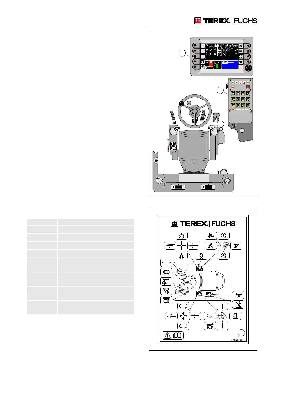
4.2 Operating concept
Permanently preset machine functions
Many machine functions are automatically
switched by the machine control unit and are
not accessible to operating personnel. In
some cases authorized service personnel can
make adjustments in the Service menu.
Switchable machine functions
Control elements are available in the cab for
the switchable machine functions. Many can
be switched directly by operating the control
element, for example, the four-way control
lever (21/1). Some are switched on via the
control panel (21/2) or the multifunction dis-
play (21/3).
Control units and control scheme
The most important control elements for the
control of the loading machine are combined
in a control scheme. In the standard version,
the loading machine is delivered with an ISO
control unit. Alternatively, other control units
can be selected.
4.2.1 Control units overview
A sign with the control scheme is located in
the cab (fig. 22). The drawing number (22/1)
indicates the control type shown.
ISO: Steering with a four-way
control lever
Fuchs: Steering with a four-way
control lever
5358609975 O&K: Steering with a four-way
control lever
Liebherr: Steering with a four-way
control lever
If the customer so wishes, the loading ma-
chine may be equipped with a special control.
Special control of the machine (if yes,
please tick)
h Additional operating instructions
BSB50620
95
C
100
C
F
0 ½ 1
09:43 11.03. 2011
MHLX XX / XXX X
1800 UPM
0 5 10 15 20 25
0 %
120 %
100 %
80 %
60 %
40 %
20 %
hFQC
1
2
3
Fig. 21 Operating concept
Fig. 22 Control scheme example