4 DISPLAY AND CONTROL ELEMENTS
4.26 MHL360 E
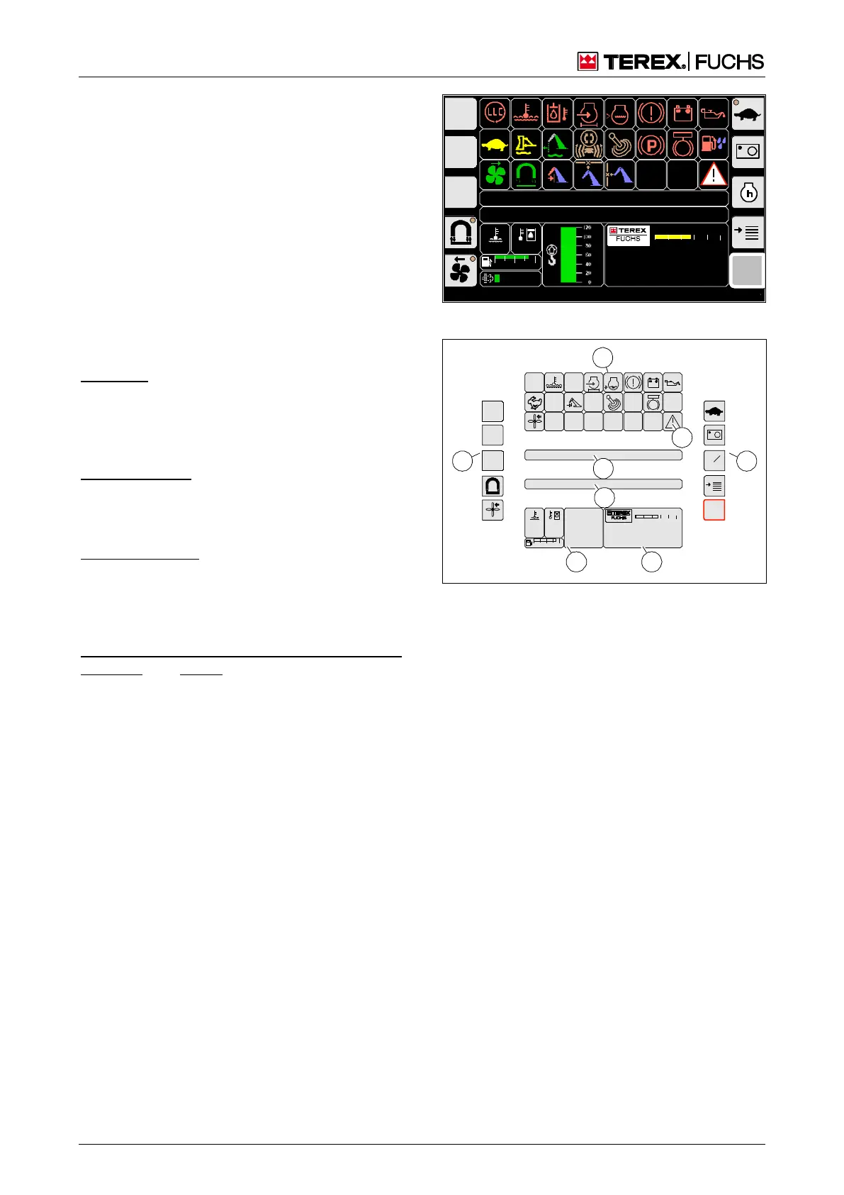
4.5 Main control display screens
4.5.1 Main control display
The main control display (Fig. 45) displays the
most important operating states of the loading
machine. It enables quick access to the most
important functions during work operation.
Call-up
The main control display automatically ap-
pears after the ignition is switched on. It con-
tinues to be displayed until a different display
screen is opened.
Structure
Indicators for the operating state and switched
machine functions can be found:
in the top area (46/2) as symbols
in the bar (46/4) as yellow text messages.
Fault messages appear:
via the flashing symbol (46/8)
in the bar (46/5) as a red text message
Measured values are indicated in area (46/6):
as a numerical value or bar
in the case of monitored functions by color
change of symbol or background
The date/time, operating hours, machine iden-
tification, and speed of the diesel engine (op-
tional) are displayed in area (46/7).
The sensitive areas (46/1 and 3) are divided
into buttons. The buttons are assigned im-
portant functions and/or additional menus.
BSB50553
F
09:43 11.03.2011
MHLXXX / XXXX
1800 UPM
0 5 10 15 20 25
120 0
ARBEITSHYDRAU LIK IST GESPERRT
FEHLERMELDUNG
95°C 75°C
0 ½ 1
9 %
BSB50557
Fig. 45 Main control display
BSB50538
95
C
100
C
0 ½ 1
09:43 1 1.03.20 11
MHL XXX / XXXX
1800 UP M
0 5 10 15 20 2 5
00:00
h
F
2
1 3
4
5
6 7
8
Fig. 46 Structure of main control display