8 TROUBLESHOOTING
8.4 MHL360 E
8.7 Malfunctions in the load limit sensing
control
Malfunctions of the load limit sensing control
(BOSCH-Rexroth) are not indicated.
Verification of the load limit sensing control
function is only possible for authorized service
personnel. Fault diagnostics can be per-
formed with the "BODEM" diagnostics soft-
ware of BOSCH-Rexroth.
In order to ensure that the machine continues
to operate in the event of malfunctions affect-
ing load limit sensing control, load limit sens-
ing control can be disconnected.
The hydraulic pump is not con-
trolled if the load limit sensing con-
trol is disconnected. This can over-
load the diesel engine to such an
extent that it will come to a stop.
This can make working conditions
dangerous (e.g. risk of falling
loads). Frequent overloading re-
duces the service life of the diesel
engine.
Therefore, when load limit sensing
control is disconnected, the ma-
chine should only be moved for
short periods of time and under re-
duced load. Load limit sensing con-
trol must be repaired immediately
by an authorized service engineer.
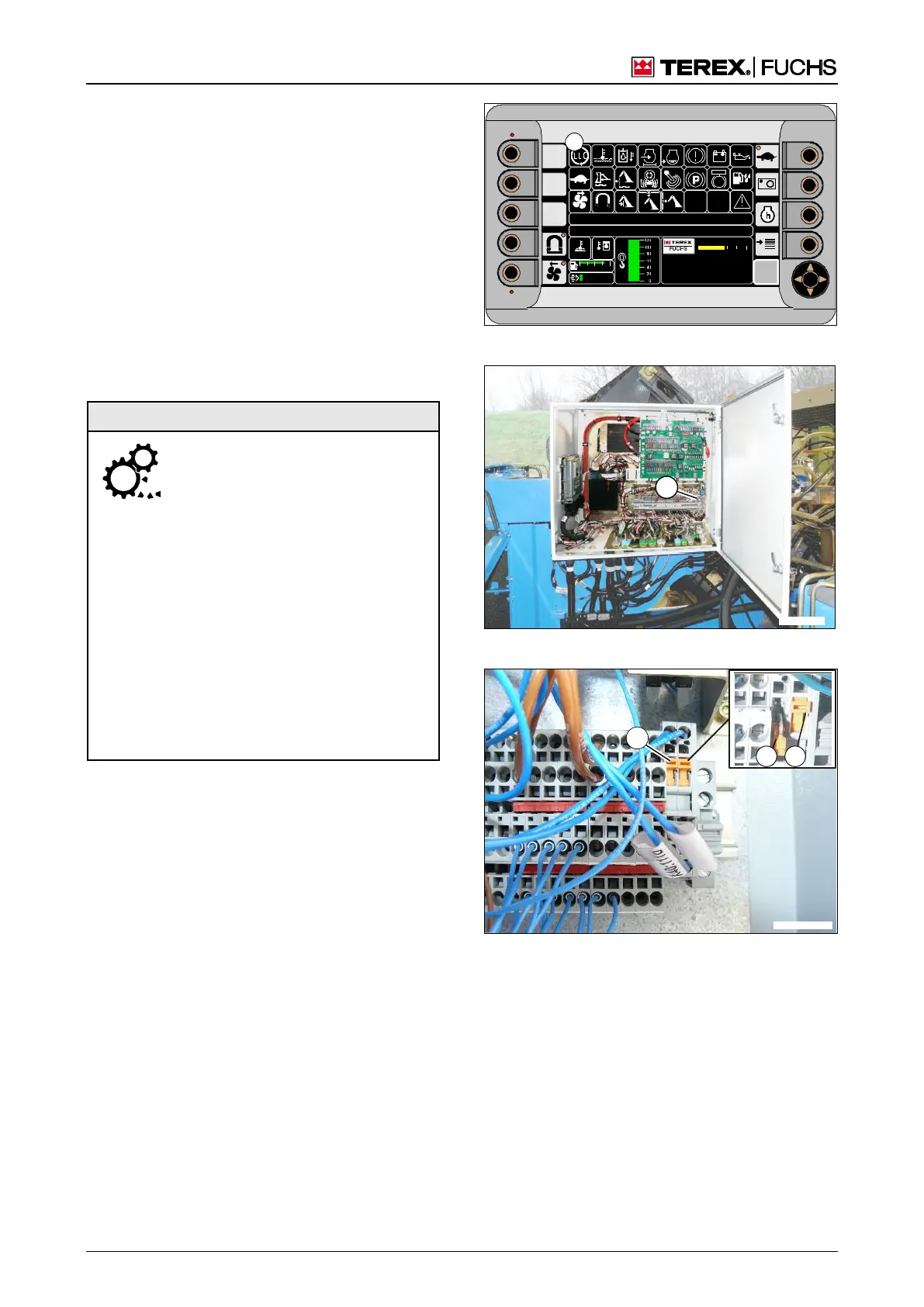
Switching off the load limit sensing control
Load limit sensing control is disconnected via
the isolating blade terminals in the lower sec-
tion of the terminal blocks in the central elec-
trical system (342/1).
►
Switch off the machine.
►
Using a screwdriver of the appropriate size,
carefully fold the isolating blade terminals
(343/1 and 2) out from the contact position.
►
Start the machine. The indicator will remain
lit, but load limit sensing control has been
taken out of operation (341/10).
►
Carefully move the machine without over-
loading the diesel engine.
F
09 :43 11 .03. 2 011
MH LX X X / XXX X
18 00 U PM
0 5 1 0 15 20 2 5
95°C 7 5°C
0 ½ 1
9 %
120 0
BSB50869
10
Fig. 341 Load limit sensing control
Fig. 342 Terminal block in central electrical system
Fig. 343 Isolating blade terminals
Malfunc
tions in
the
load
limit
sensing