CARE AND MAINTENANCE 7
MHL360 E 7.75
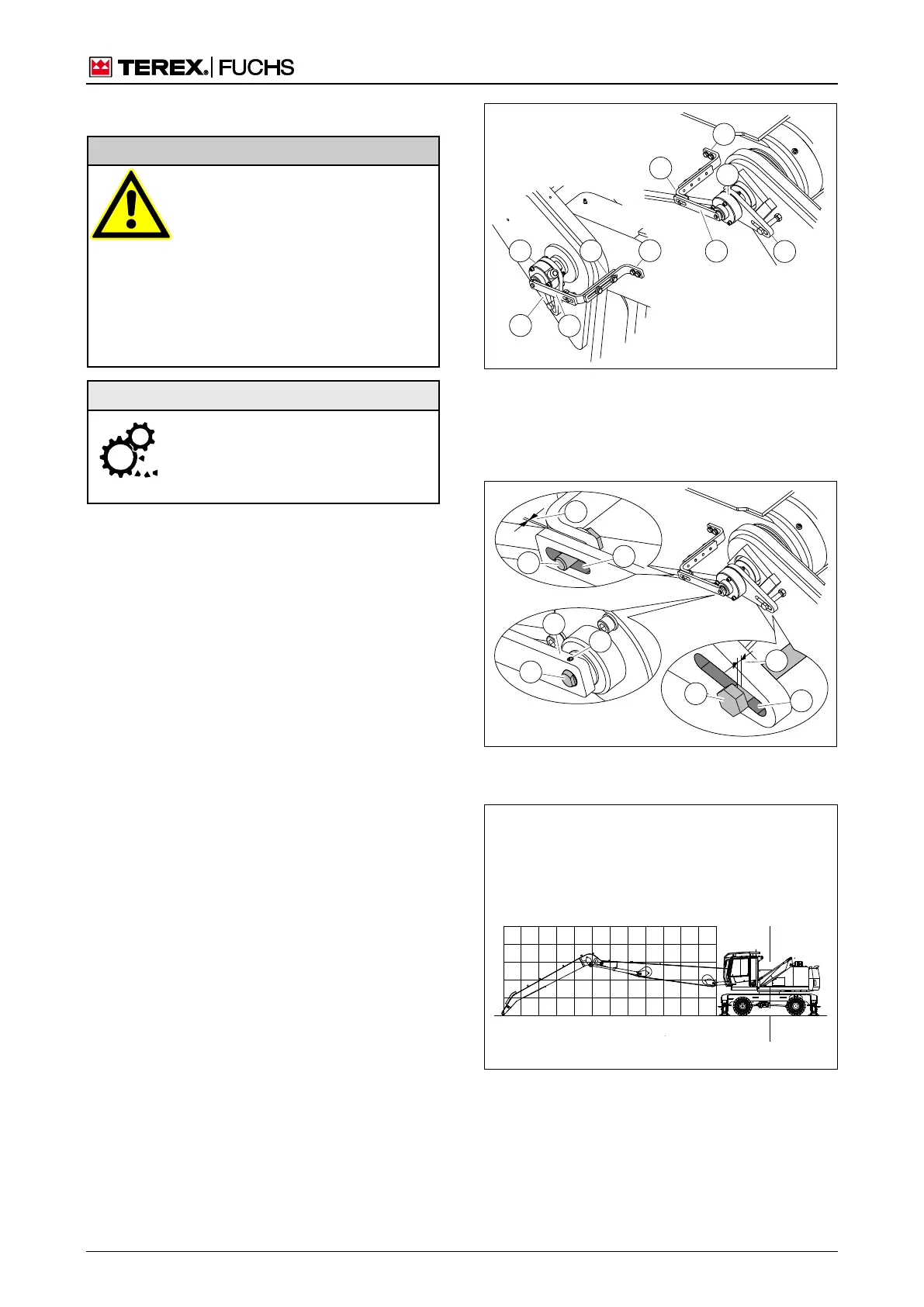
7.7.23 Angular resolvers (optional)
Risk of crushing from loading
equipment
• Only carry out a visual inspection
when the loading machine is
switched off and its pressure has
been discharged, and when the
loading equipment has been
safely lowered.
In an emergency: Administer first
aid, seek treatment from a doctor
Angular resolvers are precision com-
ponents. When working on the joining
elements, protect the angle transmit-
ter axle (335/2) against forces.
Condition and lubrication
►
Check the external condition of the angular
resolvers (334/1+4) and joining elements
(334/2-3).
►
Check that the connection between the clip
(335/1) and angle transmitter axle (335/2) via
the clamping sleeve (335/3) is free from play.
►
Check the pin (335/4) in the elongated hole
(335/5) to ensure it is guided free from play.
►
Check for play between the clips and
brackets. These must not touch one an-
other beyond the area of movement of the
loading equipment.
(335/6): 2±1 mm for boom and dipperstick.
(335/7): varies according to installation sit-
uation, but at least 1 mm.
► Lubricate the elongated holes (335/5).
Function check
►
Open the LE diagnostics display screen.
h Chapter 4.5.13.5 LMB/HRB diagnostics
►
Extend and retract the loading equipment
fully. During this process, pay attention to the
coordinates on the display screen, particularly
when changing direction. The coordinates
must not jump around or remain stationary.
►
Extend and set down the loading equip-
ment on level ground (Fig. 335). The dis-
played position may deviate from the work-
ing range diagram by ±0.25 m.
Fig. 334 Angular resolvers
1 Dipperstick angular resolvers
2 Holder
3 Clip
4 Boom angular resolvers
Fig. 335 Angular resolver details (using example of
dipperstick)
Fig. 336 Checking position of coordinate display