DISPLAY AND CONTROL ELEMENTS 4
MHL360 E 4.45
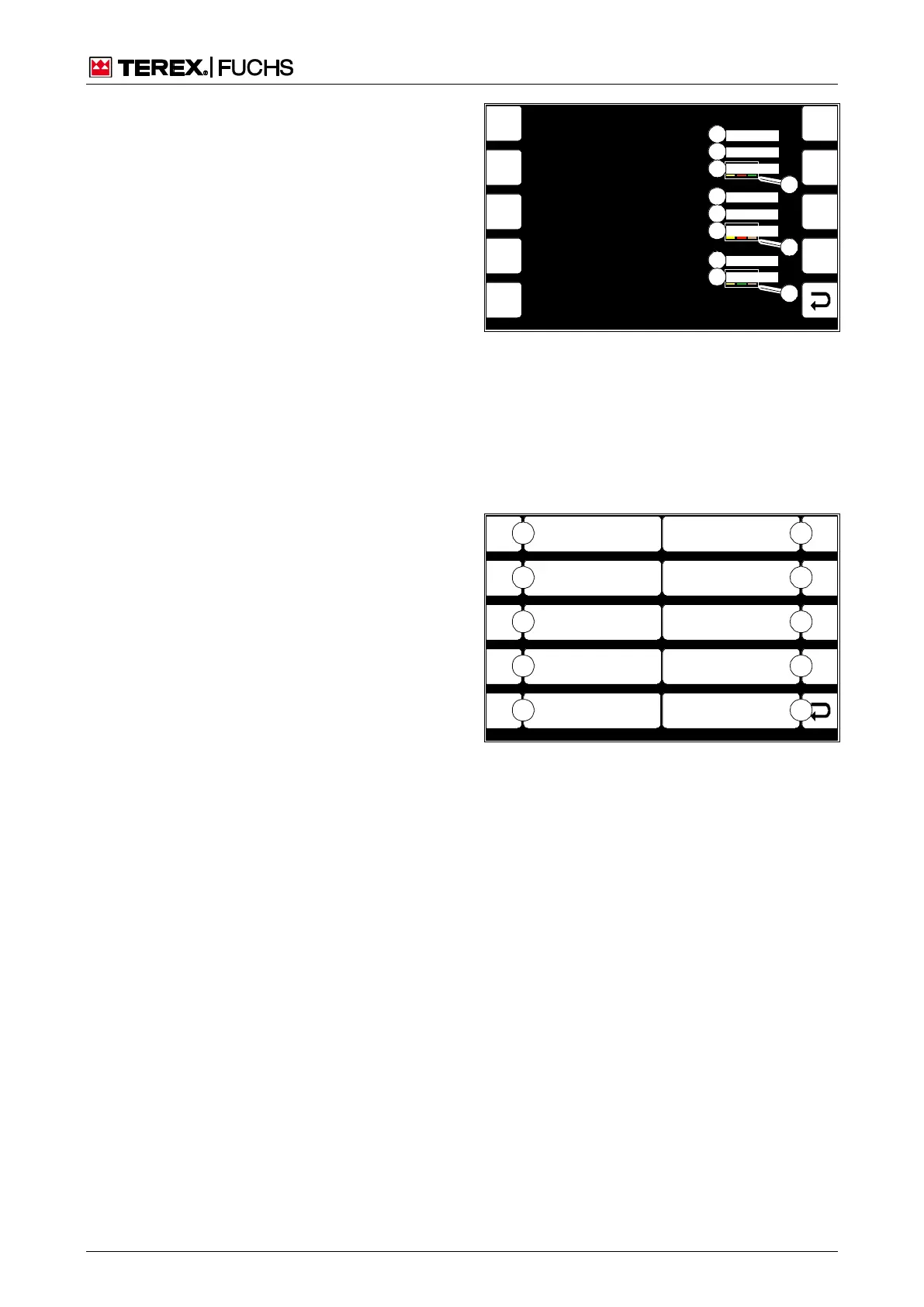
4.5.13.8 System information
This display screen shows the parameters of
the installed software. The display, main con-
trol, and option control software versions must
be compatible. The color coded first three
pairs of numbers in the version number en-
sure that checking for software updates is
carried out quickly (84/9). The pair of numbers
above a color must always be the same.
Call-up
► Main control display > Main menu > Sys-
tem information
4.5.14 User settings (optional)
This menu offers additional display screens
for displaying and changing various settings.
Call-up
►
Main control display > Main menu > User
settings
Structure
The Diagnostics menu is structured as a two-
column table.
Operating note
►
Briefly press side function key next to the
desired button (85/0-2).
or multifunction button
►
Navigate focus to button (85/0-2).
►
Briefly press button.
F3
F4
F6
F7
F8
F9
F5
6 8350 200 30
01.03.01
01.02.01.00.00
F1
F2
BSB51000
6 8350 200 10
001
01.02.00.02.00
6 8350 200 40
01.01.00.02.02
Display Software Number
Display Firmware Version
Display Software Version
Main Control Software Number
Machine Hardware Version
Main Control Software Version
Option Control Unit Software Version
Option Control Unit Software Number
1
2
3
4
5
6
7
8
9
9
9
Fig. 84 System information
1 Display software number
2 Display operating system version
3 Display software version
4 Main control software number
5 Machine hardware version
6 Main control software version
7 Option control software number
8 Option control software version
F1
F2
F3
F4
F6
F7
F8
F9
F5
BSB50630
ESC
3
2
1
0
4
8
7
6
5
9
Reversing Fan Pause Time
Set Height
And Reach Limits
Fig. 85 User settings
0 Back
1 Set height and range limits
2 Reversing fan pause time