DISPLAY AND CONTROL ELEMENTS 4
MHL360 E 4.5
4.1.3 Control panel
BSB50901
5 2
5 3
5 0
5 1
5 4
5 5
6 6
6 5
6 8
6 7
6 4
6 3
5 6 6 2
5 7
6 1
5 8 6 0
5 9
7 3
7 4
7 1
7 2
7 6
7 5
7 8
7 7
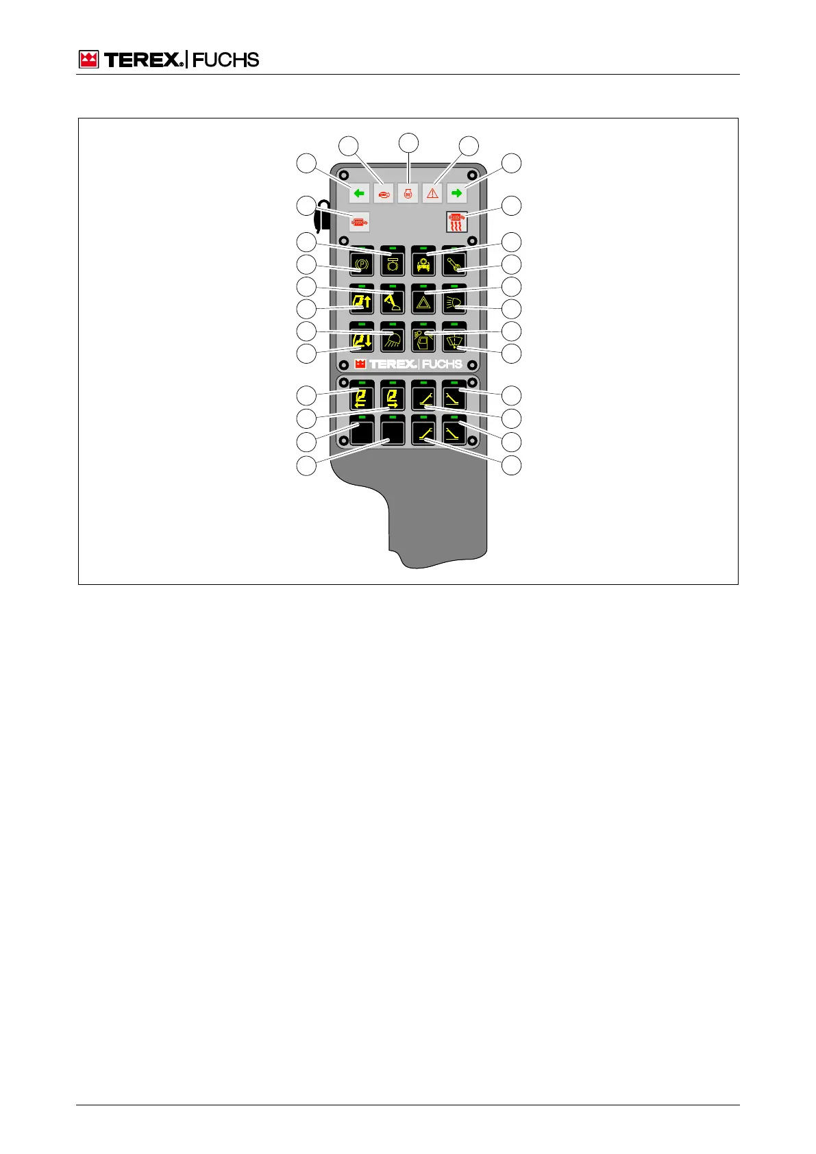
Fig. 20 Control panel
50 Pushbutton to lower cab
5
1 Loading equipment working floodlight
2 Pushbutton to raise cab
3 Activate close-range expansion button toggle (dip-
perstick)
4 Pushbutton for parking brake
5 Swing brake button toggle
6 Diesel particle filter ash lamp
7 Flashing control indicator (left)
8 Error display of the engine control system (Electron-
ic Engine Control IV)
9 Preheat display
0 Indicator – general warning / emergency operation
active
1 Flashing control indicator (right)
2 Diesel particle filter regeneration indicator/button
toggle
3 Pushbutton for oscillating axle lock release
64 Pushbutton for travel and work functions
Pushbutton function: enable work functions(
Pushbutton function: bypass cut-off of work func-
tions (emergency)
5 Pushbutton for hazard warning lights
6 Pushbutton for side lights/headlamps
7 Pushbutton for cab roof headlamps
8 Windshield wiper toggle button
1 Not Used
2 Not Used
3 Button toggle for cab backward
4 Button toggle for cab forward
5 Pushbutton for front right outrigger leg (optional)
6 Pushbutton for front left outrigger leg (optional)
7 Pushbutton for rear right outrigger leg (optional)
8 Pushbutton for rear left outrigger leg (optional)