OPERATION 5
MHL360 E 5.81
5.21 Monitoring the machine during oper-
ation
5.21.1 Monitoring strategy
After switching on, controller components
monitor various diesel engine and hydraulic
system parameters (fig. 215 and 216).
Warning levels are defined for individual pa-
rameters to prevent damage to the machine.
If the current machine data exceeds or drops
below these levels, the controler components
take action. This may involve:
Optical warnings on the main control dis-
play.
Acoustic warnings via the warning buzzer.
Machine actions being disabled or enabled
The following priority applies when multiple
warnings occur at the same time:
1 Oil pressure
2 Coolant level
3 Coolant temperature
4 Charge air temperature
To prevent uncontrolled machine
movements, the diesel engine is
not switched off. If warnings occur,
make the machine safe and switch
it off as quickly as possible. To pre-
vent damage to the machine, de-
termine and rectify the cause. Only
after doing this may you start the
diesel engine and machine back
up.
If the indicator for battery charge
control (215/16) or engine oil pres-
sure control (215/17) lights up,
switch off the diesel engine imme-
diately.
F
09 :43 11 .03. 2 011
MH LX X X / XXX X
18 00 U PM
0 5 1 0 15 20 2 5
95°C 7 5°C
0 ½ 1
9 %
120 0
BSB50637
35
36
13 14 16 17
34
33
25
1211
22
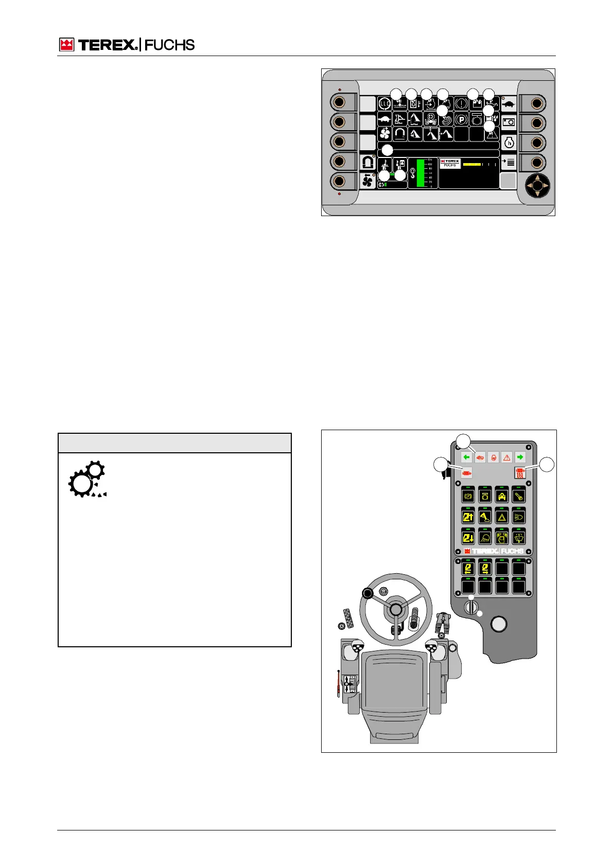
Fig. 215 Multifunction display
11 Coolant temperature or charge air temperature indi-
cator
12 Indicator for hydraulic oil temperature
13 Indicator for clogging of air filter, return filter or pres-
surized oil filter
14 Indicator for coolant level or hydraulic oil level
16 Indicator for battery charge control
17 Indicator for engine oil pressure control
22 Travel and work functions disabled indicator
25 Water in fuel indicator
33 Note text message indicator
34 Text message for the indicators
35 Indicator for the diesel engine coolant temperature in
°C and warning levels based on background color
36 Indicator for the hydraulic oil temperature in °C and
warning levels based on background color
Fig. 216 Control panel display
56 Diesel particle filter ash load
58 Error display of the engine control system
62 Regeneration of diesel particle filter
Monitor
ing the
machin
e
during
operati