4 DISPLAY AND CONTROL ELEMENTS
4.34 MHL360 E
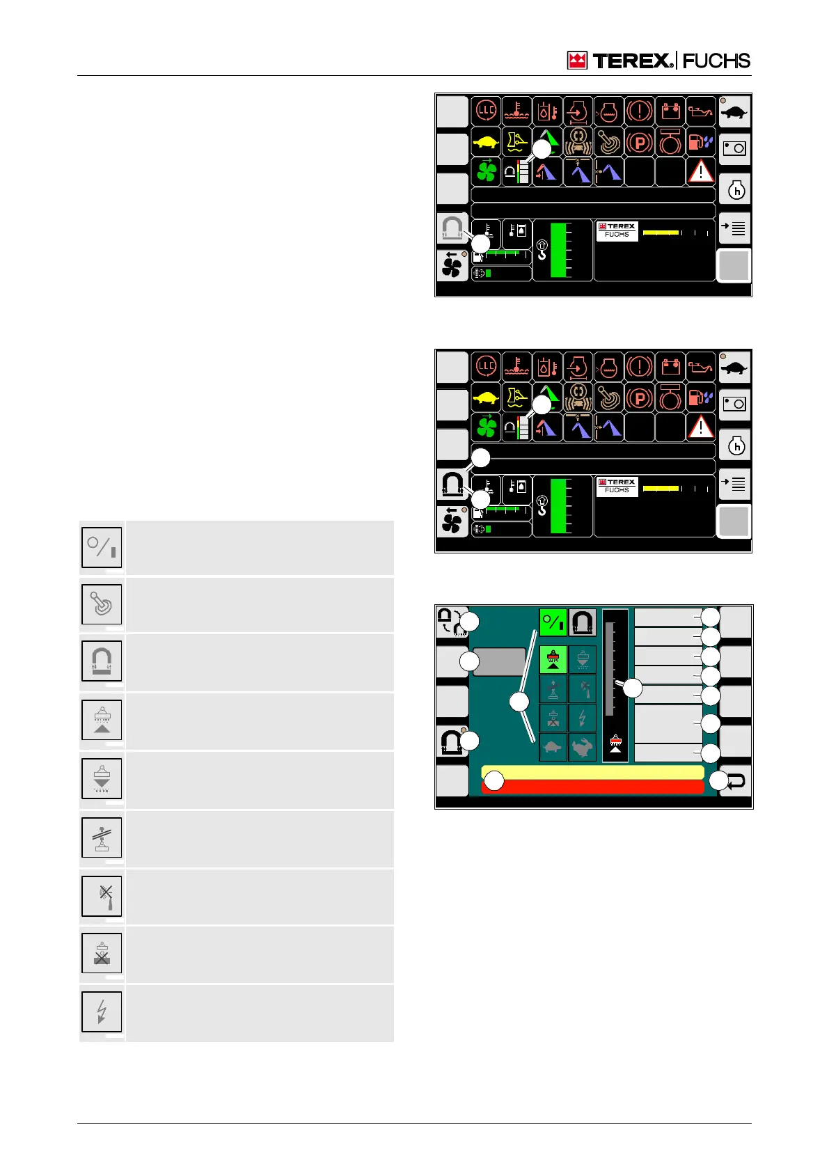
4.5.7.2 Comfort magnet system display
The comfort magnet system display shows
the current operating states and operating
data in detail, and allows you to change the
operating mode and carry out a manual ISO
guard function test. When the ignition is
switched on, the indicator appears (61/2).
Call-up
►
Start diesel engine.
►
On the main control display, use button
(62/1) to switch on the magnet system.
Structure
A symbolized LED (63/5) lights up on the but-
ton (Fig. 63). Activating this button switches
off the magnet system and closes the comfort
magnet system display. You can initiate the
ISO guard function test manually using button
(63/8). You can change the magnet system
operating mode using button (63/5).
The displays (63/18) are assigned as follows:
Green background: Magnet system is
ready to operate.
Working hydraulics disabled. Magnetiza-
tion/demagnetization not possible.
Type of symbol indicates the current op-
erating mode (symbol assignment as
shown in Fig. 60).
Green background: Magnetic plate is be-
ing magnetized/is magnetized. Lifting of
material to be loaded.
Green background: Magnetic plate is be-
ing demagnetized. Dropping of material to
be loaded.
Red symbol, white background: No mag-
netic plate connected or interruption in
cabling.
Red symbol, white background: CAN er-
ror.
Red symbol, white background: Electrical
overload. The connected magnetic plate
has overloaded the generator.
Red symbol, white background: Short
circuit in connection line or magnetic
plate.
F
09:43 11.03.2011
MHLXXX / XXXX / LE XXX
1800 UPM
0 5 10 15 20 25
120 0
ARBEITSHYDRAULIK IST GESPERRT
FEHLERMELDUNG
95°C 75°C
0 ½ 1
9 %
120
100
80
60
40
20
0
F
09:43 11.03.2011
MHLXXX / XXXX / LE XXX
1800 UPM
0 5 10 15 20 25
120 0
ARBEITSHYDRAULIK IST GESPERRT
FEHLERMELDUNG
95°C 75°C
0 ½ 1
9 %
120
100
80
60
40
20
0
BSB51150
2
1
Fig. 61 Comfort magnet system display when igni-
tion is switched on
F
09:43 11.03.2011
MHLXXX / XXXX / LE XXX
1800 UPM
0 5 10 15 20 25
120 0
ARBEITSHYDRAULIK IST GESPERRT
FEHLERMELDUNG
95°C 75°C
0 ½ 1
9 %
120
100
80
60
40
20
0
BSB51123
2
3
1
Fig. 62 Comfort magnet system display with diesel
engine running, magnet system switched off
BSB51116
ISO
100
90
80
70
60
50
40
30
20
10
0 %
CAN
0 kOhm
MAGN ET VOLTA GE
MAGN ET CURRENT
MAGN ET POWER
ELECTR. TE MP .
TORQUE
SPEED
MC U-PLC STAT US
0
0 [1/min]
0 [Nm]
0 [°C]
0 [W]
0 [A]
0 [V]
ARBEITSHYDRAULIK IST GESPERRT
FEHLERMELDUNG
Selftest
8
5
9
10
17
11
12
13
14
15
16
19
118
0
Fig. 63 Comfort magnet system display with diesel
engine running, magnet system switched on
0 Back
5 Deselect magnet system
8 ISO guard function test/Current isolation resistance
measured value
9 Select operating mode
10 MAGNET VOLTAGE
11 MAGNET CURRENT
12 MAGNET POWER
13 ELECTRONICS TEMPERATURE
14 TORQUE
15 SPEED
16 MCU CONTROL UNIT STATUS
17 Relative operating time (relative to three-minute
interval)
18 Symbols
19 Information texts, error messages, action information