DISPLAY AND CONTROL ELEMENTS 4
MHL360 E 4.43
4.5.13.6 Grease lubrication system diag-
nostics
The display screens show the operating
states and parameters for the central grease
lubrication system.
Call-up
►
Main control display > Main menu > Diag-
nostics menu > Grease lubricating system
diagnostics
►
Select desired lubricating system
Electronic pump control can be performed in
automatic or manual mode. The correspond-
ing display screens are shown.
Setup of automatic mode
When the diesel engine is running, the display
screen for automatic mode appears (Fig. 78).
The pump runs in accordance with the pa-
rameters displayed (78/1). The status of the
piston detector is monitored during the set
number of pump cycles. If a status change
takes place during these pump cycles (pause
time and pump run time) the piston has
moved in the monitored distributor. If no sta-
tus change takes place, an error message
appears (also in the main control display).
The middle area of the display screen (78/2)
indicates the current operating status of the
pump and piston detector. If the pump is run-
ning or the piston detector changes its status,
the display and text change.
The progress indicator (78/3) shows the ex-
pired and outstanding pump run time and
pause time with colored bars and percent-
ages.
Operating note
The pause time can be terminated. Then the
pump starts.
►
Briefly press side function (79/11) key.
or multifunction button
►
Navigate focus to button (79/11).
►
Briefly press button.
F1
F2
F3
F4
F6
F7
F8
F9
F5
BSB51160
ESC
Lamp Test
Diagnostics Lubrication
LE - Diagnostics
3
2
1
0
4
8
7
6
5
9 CANopen - Diagnostics
OPERATING HOURS
ECU - Diagnostics
Diagnostics Magnet System
Fig. 77 Diagnostics menu
6 Grease lubrication system diagnostics
F3
F4
F6
F7
F8
F9
F5
F1
F2
BSB50883
4 5 6
1
3
2
Uppercarriage grease lubrication system
Appointed
Pause time
Appointed
Pump run time
Appointed No. of pump runs
With detector monitoring
Remaining
Pause time
Achieved No. of pump runs
With detector monitoring
No. of pump runs
Achieved
Status change
Detected
Pump
Status
Piston detector
HIGH = GR EEN
LOW = G RAY
Fig. 78 Grease lubrication system diagnostics
1 Parameters and cycle status
2 Current operating status
3 Progress indicator
4 Pump
5 Lubricating line
6 Piston detector
F3
F4
F6
F7
F8
F9
F5
F1
F2
BSB50884
Uppercarriage grease lubrication system
Appointed
Pause time
Appointed
Pump run time
Appointed No. of pump runs
With detector monitoring
Remaining
Pause time
Achieved No. of pump runs
With detector monitoring
No. of pump runs
Achieved
Status change
Detected
Pump
Status
Piston detector
HIGH = GR EEN
LOW = G RAY
2
3
4
5
7
9 8
10
1
11
Remaining
Pump run time
6
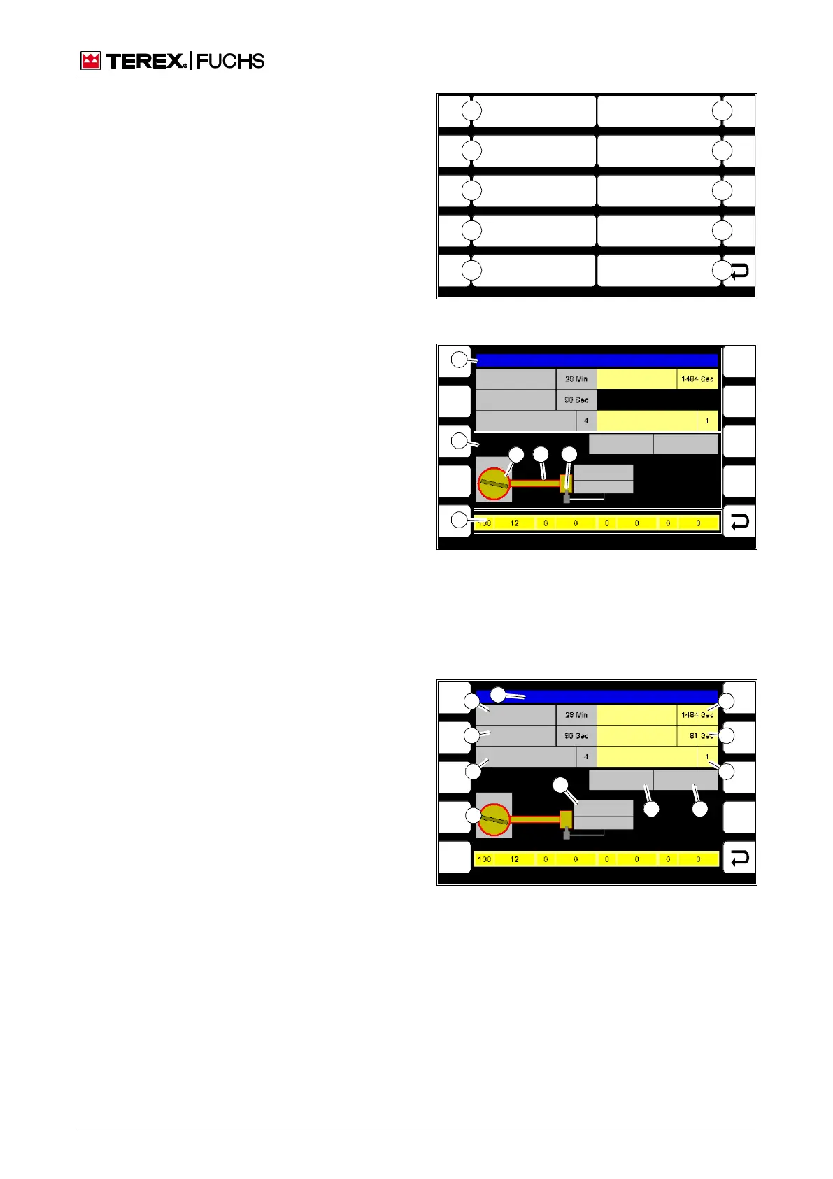
Fig. 79 Automatic mode
1 Selected grease lubrication system
2 Set pause time
3 Set pump run time
4 Set number of pump cycles with detector monitoring
5 Remaining pause time
6 Remaining pump run time
7 Achieved number of pump cycles with detector moni-
toring
8 Status change detected
9 Number of pump cycles reached
10 Status of piston detector; HIGH= green LOW= gray
6
Grease
lubricati
on
system
diagnos