OPERATION 5
MHL360 E 5.35
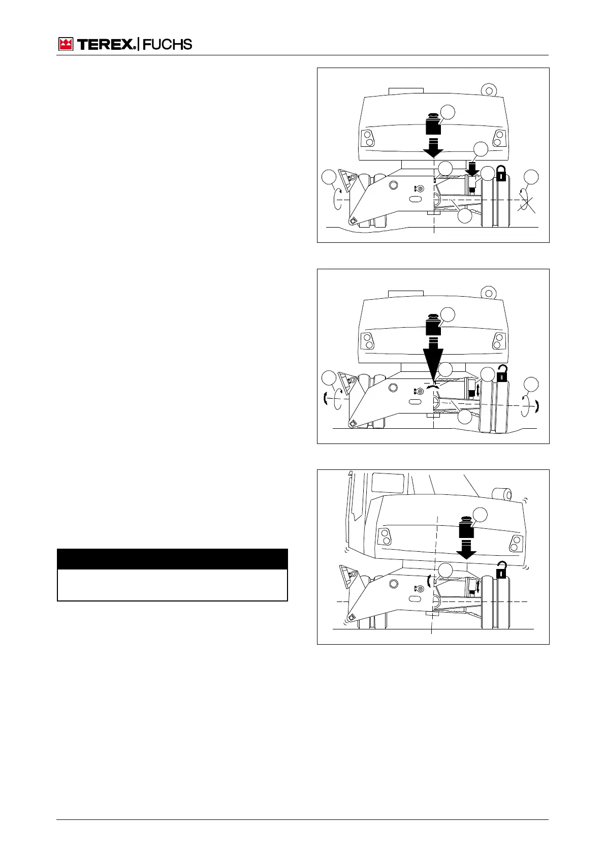
5.14 Locking or unlocking the oscillating
axle
The oscillating axle is provided to compensate
for uneven ground. It is pivot-mounted (146/4)
and is hydraulically locked or unlocked via the
oscillating axle cylinders (146/5).
In normal mode, the oscillating axle is locked.
The oscillating axle cylinders (146/5) lock the
axles (146/3). The load is distributed in a sta-
ble manner via uppercarriage and loading
device (146/7) over the axle (146/3) to the
wheels. If the loading machine is driven over a
large uneven area, however, a wheel will no
longer have sufficient ground traction. It ro-
tates (146/2); the opposite wheel is stationary
(146/1).
If the oscillating axle is unlocked, the oscillat-
ing axle cylinders (147/5) do not block the
axle (147/3). The latter pivots within the oscil-
lating axle bearing (147/4), both wheels touch
the ground. However, the load that is distrib-
uted via the uppercarriage and loading
equipment (147/6) is only distributed over the
oscillating axle bearing (147/4) to the axle
(147/3) and wheels (147/1 and 2).
If the uppercarriage is longitudinally aligned
with the undercarriage, no greater tipping
torque is produced with the oscillating axle
unlocked. If the uppercarriage is turned, the
center of gravity (148/1) moves away from the
oscillating axle bearing (148/2). n The load-
ing machine becomes unstable and leans to
the side.
5.14.1 n Safety rules
Risk of fatal injuries from overturning load-
If the oscillating axle is unlocked, the stability
of the loading machine is reduced.
Loading machine is on wheels
For the slewing and loading operations, lock
oscillating axle.
For travel operation (without load) unlock
oscillating axle.
Drive with a load only with the loading de-
vice over the steering axle.
Fig. 146 Oscillating axle locked
Fig. 147 Oscillating axle unlocked
Fig. 148 Oscillating axle unlocked
Locking
or
unlocki
ng the
oscillati