4 DISPLAY AND CONTROL ELEMENTS
4.24 MHL360 E
BSB50746
09:43 11.03.2011
MHLXXX / XXXX / LE XXX
1800 UPM
0 5 1 0 1 5 2 0 2 5
120 0
ARBEITSHYDRAULIK IST GESPERRT
FEHLERMELDUNG
95°C 75°C
0 ½ 1
9 %
F
3 4
3 5 3 6
3 7
3 8
3 9
4
9
3
8
2
7
1
6
0
5
1 0 11 1 2
1 3
1 4 1 5 1 6 1 7
1 8
1 9 2 0
2 1 2 2
2 3
2 4
2 5
2 6
2 7
2 8 2 9 3 0 3 1 3 2 3 3
120
100
8 0
6 0
4 0
2 0
0
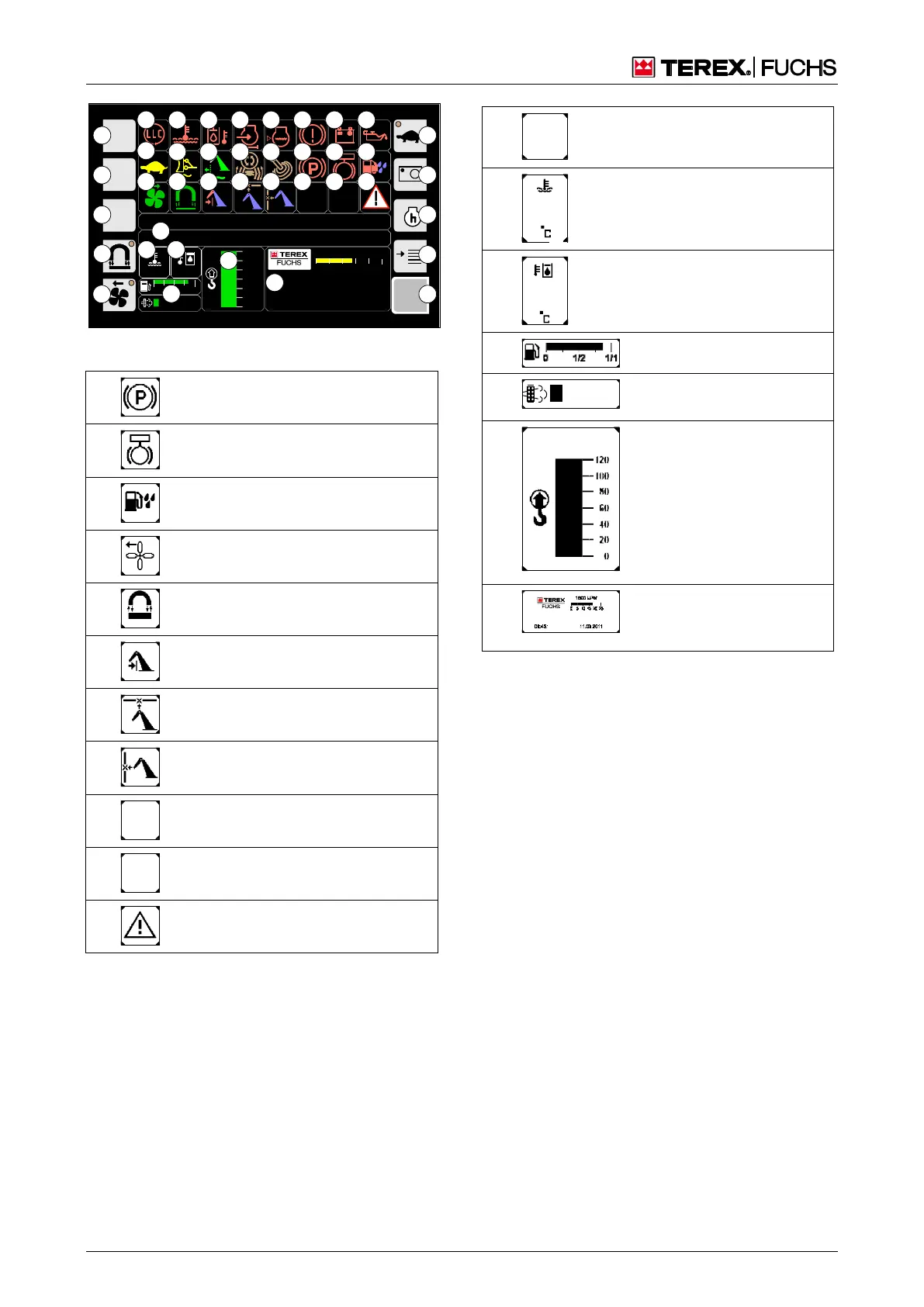
Fig. 43 Symbols on the main control display
Indicator – parking brake
24
Indicator – swing brake
25
Indicator – water in fuel
Indicator - reversing fan
Indicator - magnet system
Indicator - close-range expansion
(dipperstick)
Indicator – height limitation active (op-
tional)
Indicator – range limiting active (op-
tional)
Indicator - note message text!
B SB50 716
XXXXX XX
XXXXX XX
Indicator – diesel engine
coolant temperature (in °C)
Indicator – hydraulic oil tem-
perature (in °C)
37
Display – fuel level
Indicator - diesel particle
filter loading
Speed indicator (optional),
time, date, operating hours,
loading equipment