Chapter 2: PRODUCT DESCRIPTIONS
1. MAXIMUM SYSTEM EXAMPLE
2-2
1. MAXIMUM SYSTEM EXAMPLE
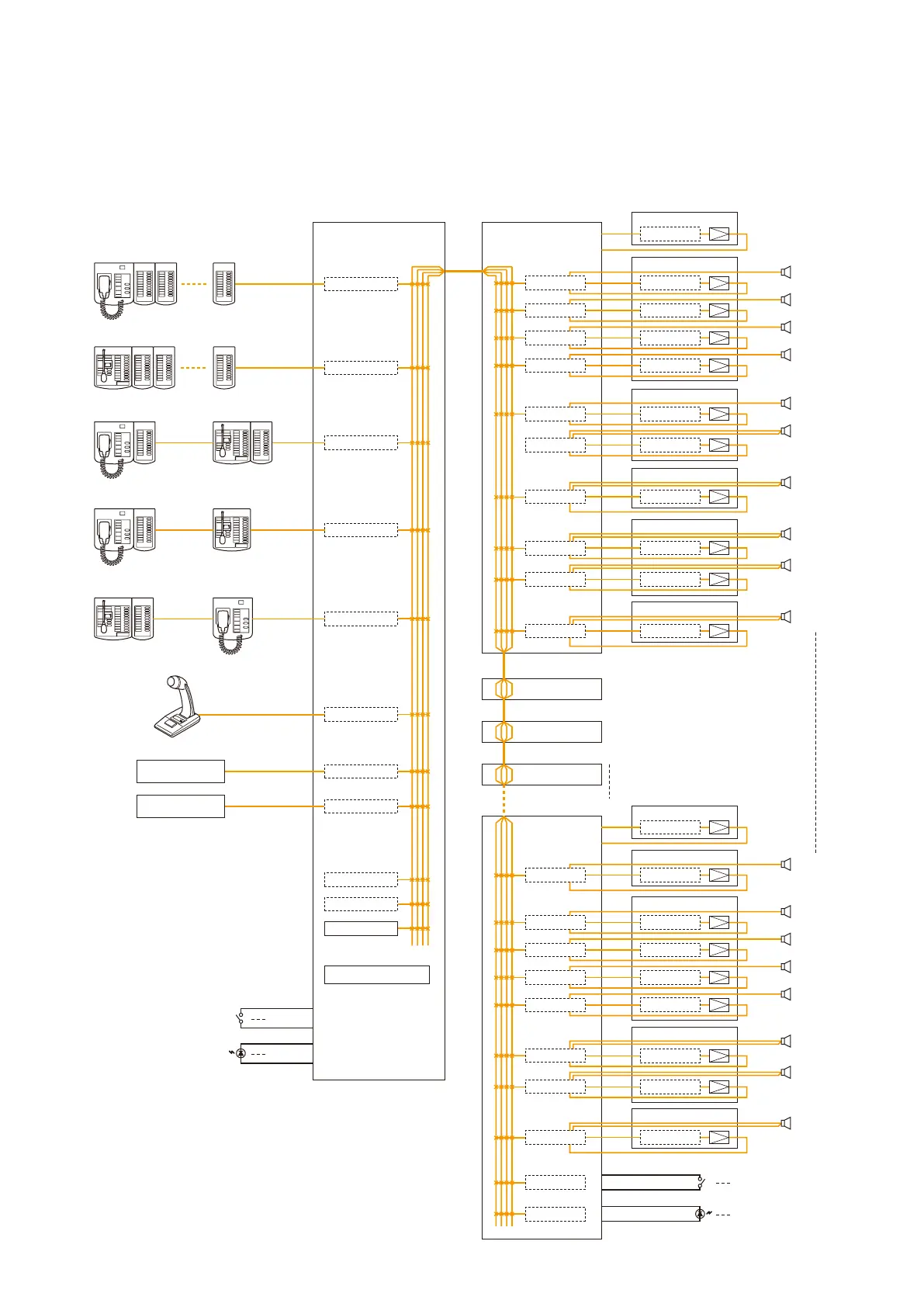
1.1. Block Diagram
The following block diagram shows the maximum size system that can be assembled with the VX-2000 Series.
Cassette Player
CD Player
RM-200XF + RM-210 x 10
RM-200X + RM-210 x 9
RM-200XF + RM-210 RM-200X + RM-210
RM-200XF + RM-210 RM-200X
RM-200X + RM-210 RM-200XF
PM-660U
Control Input x 16
Control Output x 16
VX-2000SF No.2
VX-2000SF No.3
VX-2000SF No.4
VX-2000SF No.8
ZONE 1
SF-1
Standby Amplifier
x 16
x 16
x 16
x 16
VX-200XR
VX-200XR
VX-200XR
VX-200XR
VX-200XR
VX-200XI
U-01R
EV-200 No.1
EV-200 No.2
Chime
Internal Timer
U-01R
VX-200SZ VP-200VX
VP-200VX
VP-200VX
VP-200VX
VP-200VX
VP-200VX
VP-200VX
VP-200VX
VP-200VX
VP-200VX
VP-200VX
VP-200VX
VP-200VX
VP-200VX
VP-200VX
VP-200VX
VP-200VX
VP-200VX
VP-200VX
VP-200VX
VX-200SZ
VX-200SZ
VX-200SZ
VX-200SZ
VX-200SP
VX-200SP
VX-200SP
VX-200SP
VX-200SP
VX-200SZ
VX-200SZ
VX-200SZ
VX-200SZ
VX-200SP
VX-200SP
VX-200SP
VX-200SI
VX-200SO
VX-200SZ
ZONE 2
ZONE 3
ZONE 4
ZONE 6
ZONE 7
VP-2064
ZONE 5
VP-2122
VP-2241
ZONE 9
ZONE 8
ZONE 10
VP-2122
VP-2421
VP-2421
ZONE 72
SF-8
Standby Amplifier
*
*
ZONE 73
ZONE 74
ZONE 75
ZONE 78
VP-2064
VP-2241
ZONE 71
VP-2241
ZONE 77
ZONE 76
VP-2122
VP-2241
* Available when the label on each packing box of the
VX-2000 system components (VX-2000, VX-2000SF,
RM-200X, and RM-200XF) indicates "EN80," and the
Setting Software Version is 3.0 or later.