Chapter 8: INSTALLATION AND SETTING PROCEDURES (HARDWARE)
5. VP-3154, VP-3304 AND VP-3504 POWER AMPLIFIERS
8-43
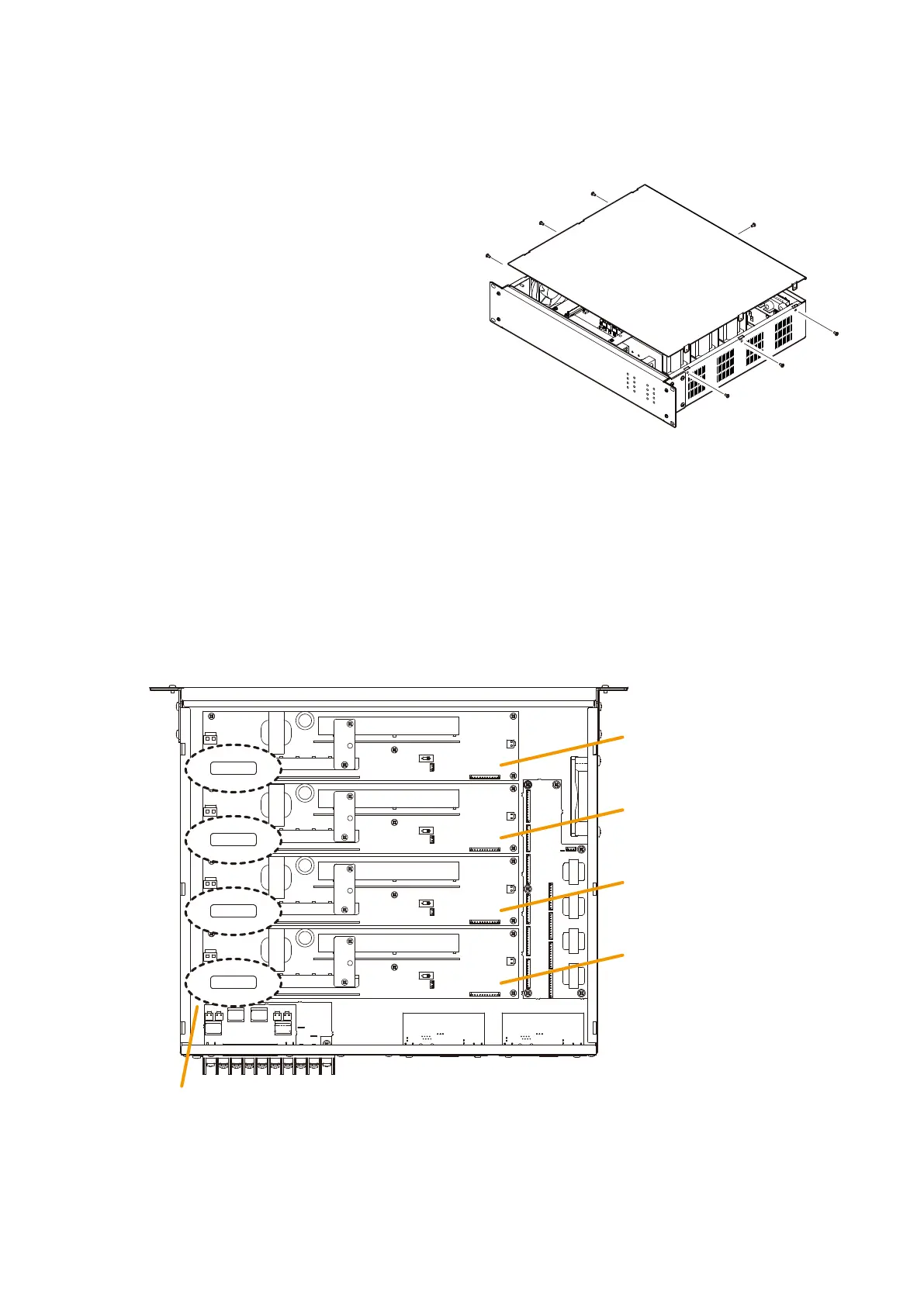
5.4. Replacing the Fuse
Whenafusehasblown,thecorrespondingchannelstatusindicatorontheunit’sfrontpanelgoesout.
In this case, replace the fuse mounted on the Channel pc board inside the unit.
Step 1. Remove the top panel.
Step 3. Replace the top panel.
Step 2. Replace the blown fuse on the corresponding Channel pc board with a new one.
Note
When replacing the fuse, be sure to use the same Blade-type of fuse, of which rating differs depending
on the models as follows.
VP-3504: 30 A
VP-3304: 20 A
VP-3154: 10 A
Rear side
[Top view (with the top panel removed)]
Channel 1
PC board
Channel 2
PC board
Channel 3
PC board
Channel 4
PC board
Blade-type fuse
30
30
30
30
The figure below shows the VP-3504.