Chapter 9: CONNECTIONS
6. CONNECTION CABLE PIN ASSIGNMENT
9-16
6. CONNECTION CABLE PIN ASSIGNMENT
The pin assignment of the RJ45 connector used to connect one or both ends of the connection cable is
explained here.
6.1. RJ45 Connector-to-RJ45 Connector Connections
Connect an RJ45 connector to both ends of the Cat. 5 STP cable and make the following connections:
[Source to Connect] [Source to be Connected to]
Component Connector Name Component Connector Name
VX-2000 DATA LINK VX-2000SF DATA LINK
VX-2000 AUDIO LINK OUT VX-2000SF AUDIO LINK IN
VX-2000SF AUDIO LINK OUT Next VX-2000SF AUDIO LINK IN
VX-2000SF DATA LINK Next VX-2000SF DATA LINK
VX-2000SF STANDBY PA LINK VP-200VX/VP-3000 series PA LINK
VX-2000SF DS-SF LINK 1, 2 VX-2000DS/3000DS
DS-SF LINK/DS LINK IN
VX-200SP PA LINK VP-200VX/VP-3000 series PA LINK
VX-200SZ PA LINK VP-200VX/VP-3000 series PA LINK
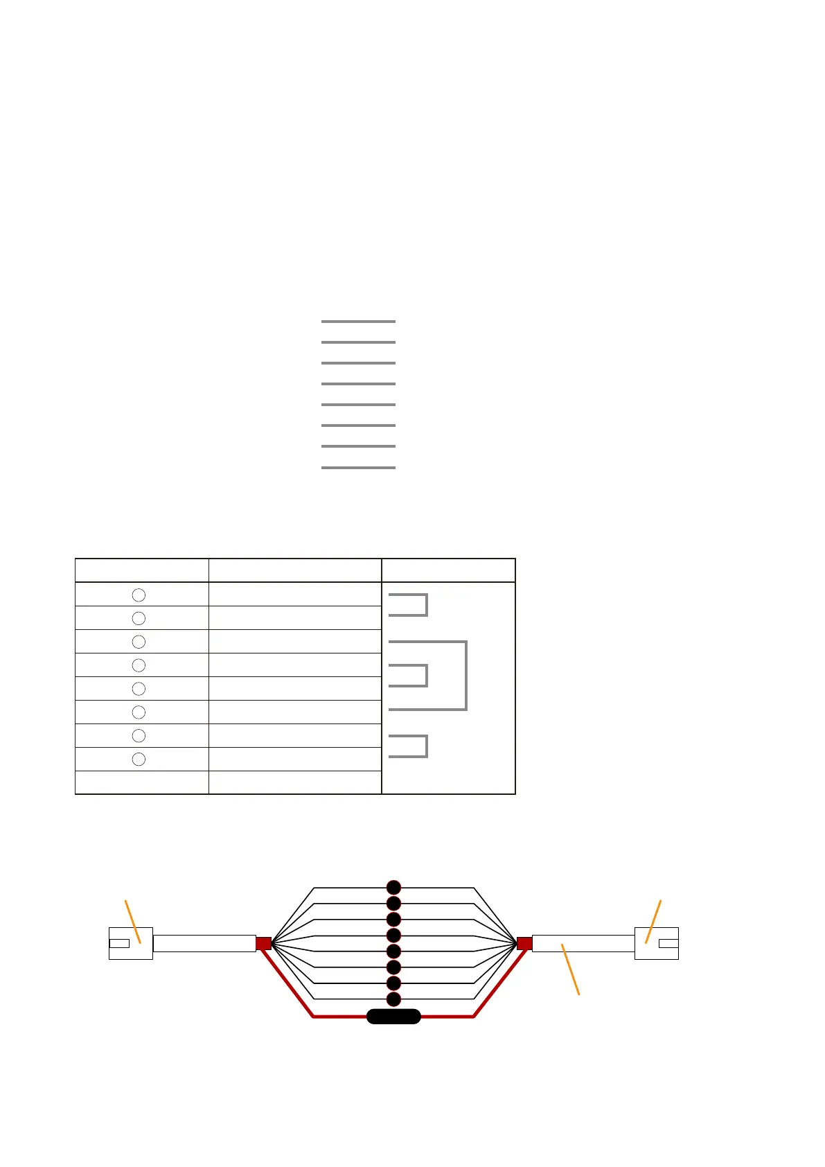
[RJ45 connector pin assignment]
RJ45 connector
Pin No.
RJ45 connector
RJ45 connector
Cat. 5 STP cable
1
2
5
6
3
4
7
8
Shield
* Differs from cable makers. In wiring,
refer to the cable specifications for
colour.
RJ45 Pin No. Colour* Pair
Orange / white
Orange
Green / white
Blue
Blue / white
Green
Brown / white
Brown
Shield Shield
1
2
3
4
5
6
7
8