Chapter 2: PRODUCT DESCRIPTIONS
2. NOMENCLATURE AND FUNCTIONS
2-21
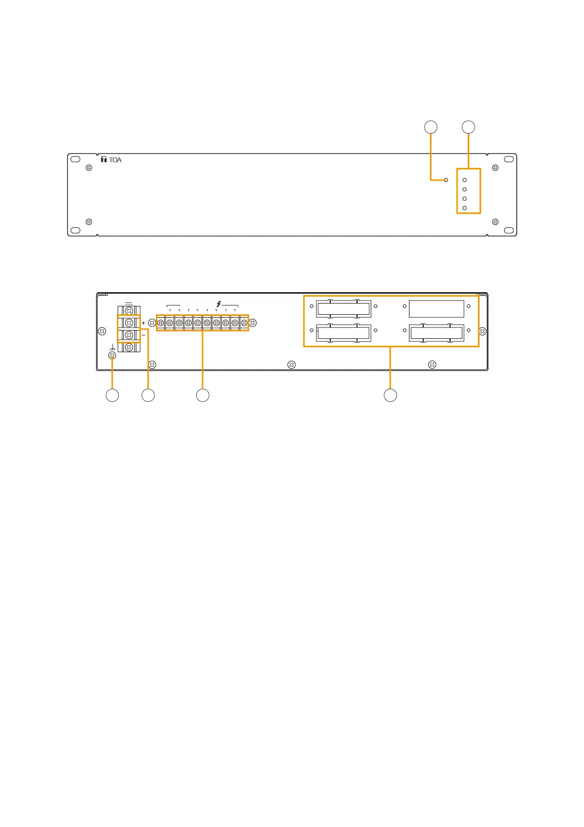
2.14. Power Amplifiers VP-2064, VP-2122, VP-2241, and VP-2421
CH2
POWEROVERHEAT
CH4
CH3
CH1
POWER AMPLIFIER 4 x 60W VP-2064
28 V4.8 A
DC POWER IN
CH3 CH1
CH4 CH2
PA OUT (SP LINE)
CH
CH1
CH
CH2
CH
CH3
CH
CH4
[Front]
[Rear]
3
4
5
6
This figure shows VP-2064.
This figure shows VP-2064.
1. Channel power indicator [POWER]
Only the lamp for the input module-mounted
channel lights green when the power is supplied.
•Off: VP-200VXnotinstalled
•Lightsgreen: In-usestatus
•Lightsred: StandbystatusorDCfuseblowout
2. Overheat indicator [OVERHEAT]
If the internals of the power amplifier overheat, this
indicator lights yellow and the power amplifier's
operation is stopped.
3. Ground terminal
4. DC power input [DC POWER IN]
Connects to the VX-2000DS/3000DS unit's DC
POWER OUT terminal.
5. Output terminal [PA OUT (SP LINE)]
Connects to the power amplifier input terminal of
the VX-200SP or VX-200SZ module mounted in
the VX-2000SF Surveillance Frame.
The speaker line output voltage can be changed
with an internal modification.
For the modification procedure, refer to
p. 8-34.
6. Module slot
Insert the VP-200VX Power Amplifier Input module
into this slot.
Four different configurations of power amplifiers can be used in the VX-2000 system: 60 W x 4 channels, 120
W x 2 channels, 240 W x1 channel, and 420 W x 1 channel versions. Mount a VP-200VX Power Amplifier Input
module for each channel used.