Chapter 8: INSTALLATION AND SETTING PROCEDURES (HARDWARE)
2. VX-2000, VX-200XR, VX-200XI, AND EV-200
8-19
2.5. Mounting the EV-200 Voice Announcement Board on the VX-2000 System Manager
Do not handle unless your body is static-free because some of the assembled components are sensitive
to static electricity.
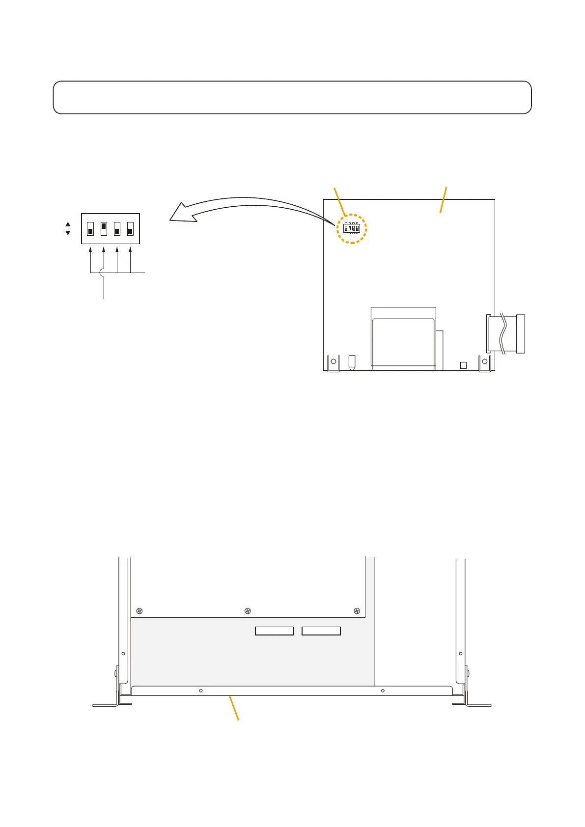
Step 1. Conrm the DIPswitch on the EV-200 Boardis set for the factory-preset position as shown in the
gure.
1
2
3
4
O
F
F
SW 1
EV-200 surveillance signal output on-off (Switch 2)
Be sure to set to ON. (A 1 kHz signal output)
DIP switch
DIP switch
ON
OFF
EV-200 Board
Always set to OFF.
(ON position is for factory test.)
EV-200 surveillance signal output (Switch 2)
The EV-200 board continuously transmits a 1 kHz sine wave signal to the VX-2000 System Manager
when the EV-200 Board is not reproducing audio signals. The VX-2000 detects the existence of the 1
kHz signal. When the 1 kHz signal does not exist with the EV-200 not in use, the VX-2000 judges the
board's failure and causes the FAULT indicator to light.
Step 2. Remove both the top and front panels.
Refer to
p. 8-15 "2.1. Removing the VX-2000's Top and Front Panels."
ThegurebelowisthetopviewofVX-2000inside.TheEV1andEV2connectorsareusedtoconnect
EV-200 boards.
EV2 CN502EV1 CN501
CPU Board
IO Board
VX-2000 panel chasis