Chapter 9: CONNECTIONS
6. CONNECTION CABLE PIN ASSIGNMENT
9-17
RM-200XF or RM-200X
Assignment
RJ45 Pin No. Colour Pair VX-200XR Assignment
Monitor in (H) Orange / white Monitor out (H)
Monitor in (C) Orange Monitor out (C)
RM data Green / white RM data
Audio out (H) Blue Audio in (H)
Audio out (C) Blue / white Audio in (C)
RM data Green RM data
DC power in (+) Brown / white DC power out (+)
DC power in (–) Brown DC power out (–)
Shield Shield Shield Shield
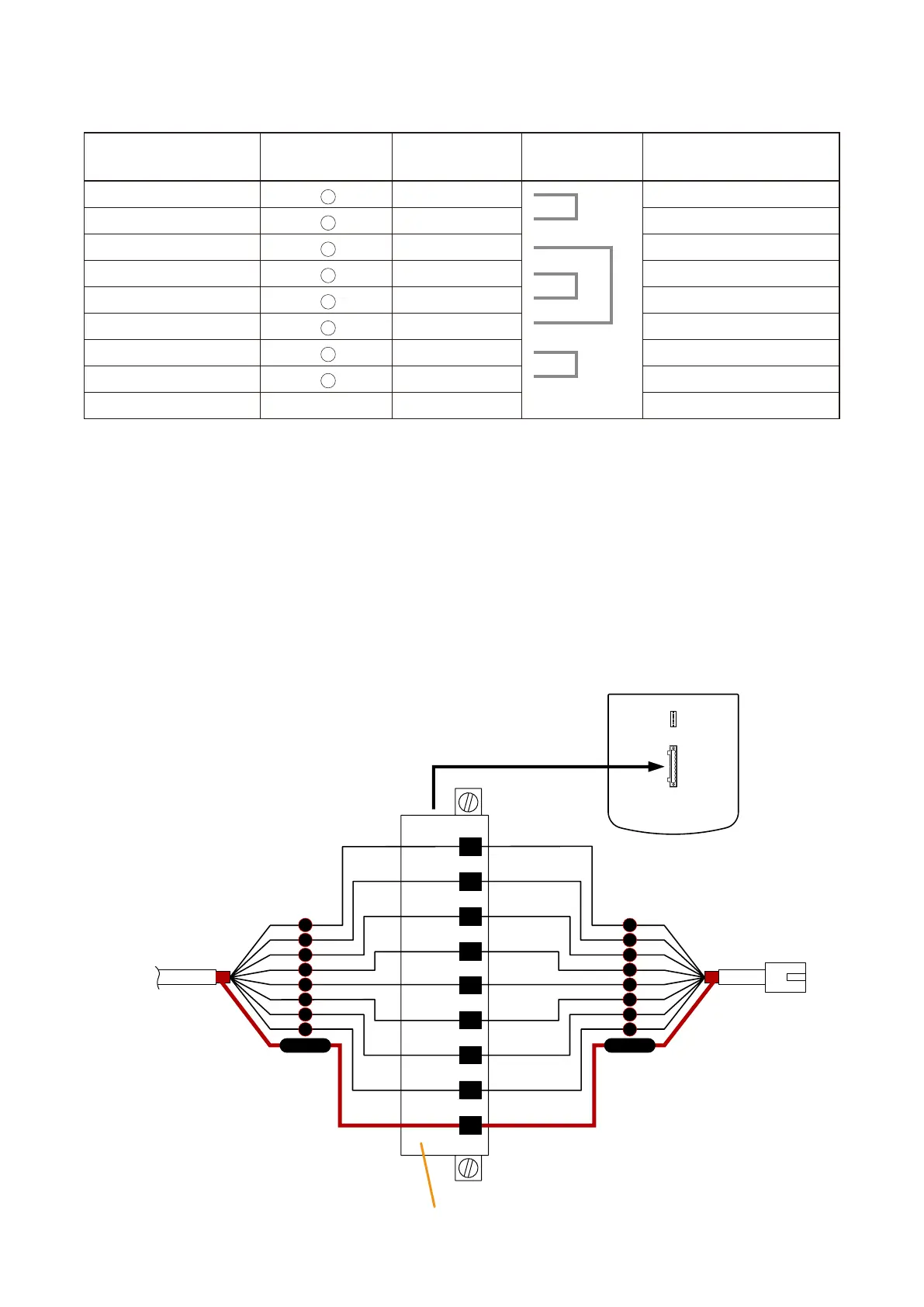
6.2. VX-200XR to Remote Microphone (RM-200XF or RM-200X) Connections
Remote Microphones can be connected by way of daisy-chain or free topology configurations.
Caution
Make sure to connect the Shield terminals of the RM-200XF, RM-200X, and VX-200XR Remote Microphone
Input Module to the Cat. 5 STP cable shield. If not connected in this way, the system will not operate correctly
when the CPU switch is turned OFF.
•Daisy-chainconnectionbetweenRM-200XFandVX-200XR
RJ45 connector
Pin No.
To VX-200XR
Plug-in screw terminal (supplied with the RM-200XF)
1
2
5
6
3
4
7
8
Shield
1
2
5
6
3
4
7
8
Shield
To the next RM-200XF
RM-200X
Monitor in (H)
Monitor in (C)
RM data
Audio out (H)
Audio out (C)
RM data
DC power in (+)
DC power in (–)
Shield
RM-200XF Bottom
1
2
3
4
5
6
7
8