Chapter 2: PRODUCT DESCRIPTIONS
2. NOMENCLATURE AND FUNCTIONS
2-17
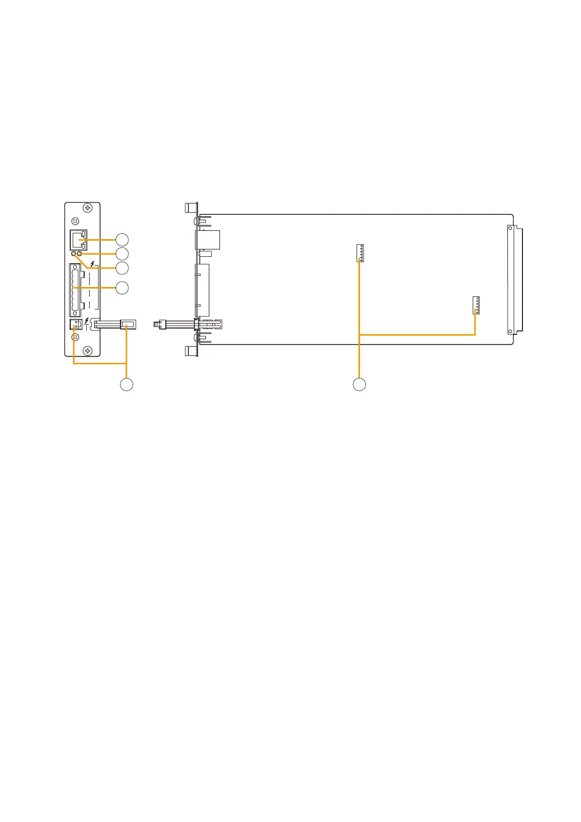
2.10. Impedance Detection Module VX-200SZ
STANDBY
PA BUS
VX-200SZ
PA
LINK
RUN
SET
H
SP
OUT
CH
PA
IN
CN1 N2C
ATT
CTRL
3
4
5
6
1
2
1.Poweramplierlinkconnector[PALINK]
This RJ45 connector connects to the PA LINK
connector of the VP-200VX Power Amplifier Input
module or the VP-3000 series Power Amplifier.
Both LEDs on this connector are not used.
2. Run indicator [RUN]
Flashes green when system equipment is operating
correctly.
3. Set indicator [SET]
Indicates system initialisation setting status.
•Off: Initialisationundone(factory-set)
•Flashesgreen: Initialisationinprogress
•Lightsgreen: Initialisationcompleted
4. VX-200SZ plug-in screw connector
Signal lines to be connected are shown below:
•Externalattenuatorcontrol[ATTCTRL]
Permits connection of 4-wire system attenuators.
For the connection instructions, refer to p. 9-7.
The attenuator bypass method can be changed
from relay to photocoupler type. For the
modification instructions, refer to p. 8-29.
•Speakeroutput[SPOUT]
Connects to the speaker.
•Poweramplifierinput[PAIN]
Connects to the power amplifier's speaker
output.
5.Standbyamplierbusconnector
[STANDBY PA BUS]
Connects to all outputs of a single VX-2000SF unit
to be switched over to the standby amplifier when
the power amplifier fails.
For details, refer to
p. 9-9, 9-10 for Standby
Amplifier Connection.
6. VX-200SE mounting connector
Used to mount the VX-200SE Equaliser card.
Install this module in the VX-2000SF Surveillance Frame to detect speaker line short circuits, open circuits by
comparing impedance readings, and ground fault.
Important Note
When combining this module with the VP-200VX BGM Input Module, then the signal level applied to the VP-
200VX's external input should be low, i.e. about 10 dB below the rated level. The level can also be reduced by
the volume adjustment.