Chapter 2: PRODUCT DESCRIPTIONS
2. NOMENCLATURE AND FUNCTIONS
2-19
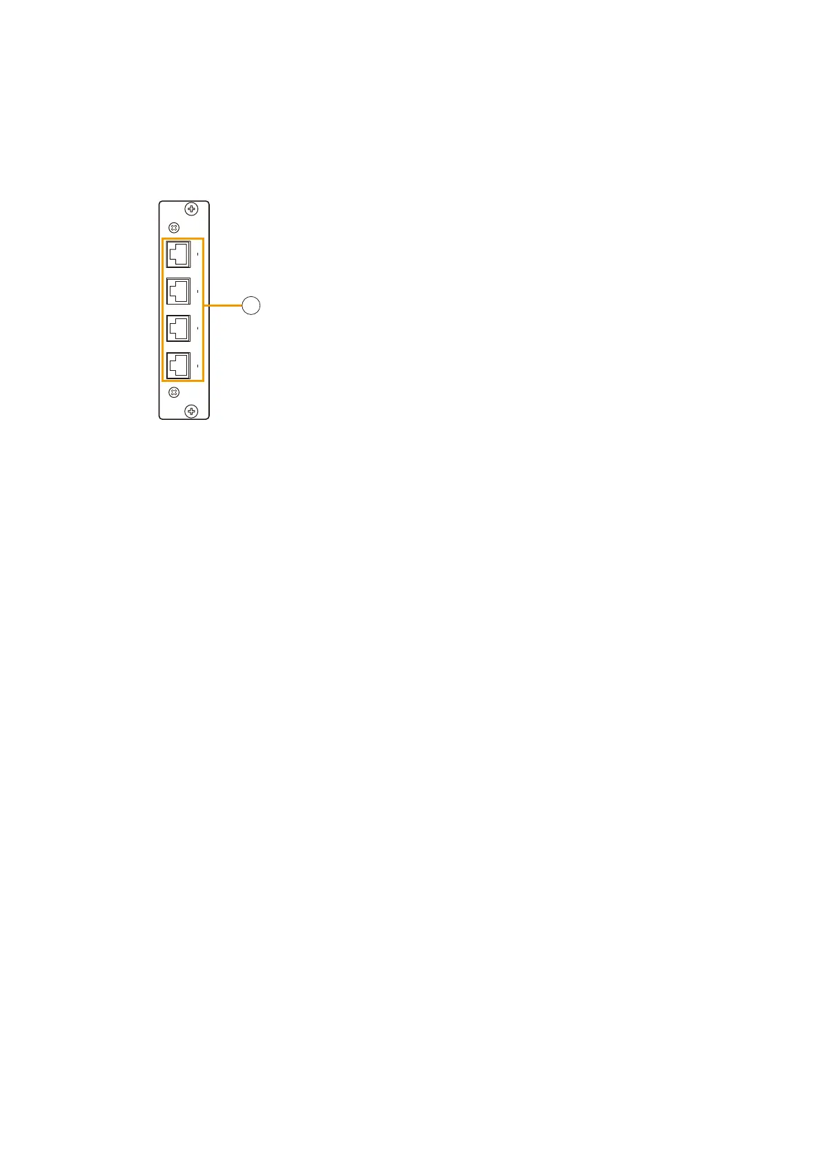
2.12. Control Input Module VX-200SI
VX-200SI
1
4
5
8
9
12
13
16
CTRL
IN
[Front]
1
1. Control input connector [CTRL IN 1 – 4, 5 – 8, 9 – 12, 13 – 16]
This RJ45 connector connects to equipment components that output
control signals.
The CTRL 1 – 4 input can be insulated by internal modification.
For the modification instructions, refer to p. 8-32.
Logic (make or break) for the CTRL 1 – 16 input can also be switched
by changing the position of the internal switch. For the switch position
selection, refer to p. 8-31.
Install this module in the VX-2000SF Surveillance Frame when in use.
The VX-200SI receives a contact signal from connected external equipment and controls the system.
By increasing the number of Control input modules, the system can have up to 128 control inputs, including the
System Manager's 16 control inputs.