Chapter 3: SYSTEM OPERATION OUTLINE
3. AMPLIFIER STANDBY FUNCTIONS
3-5
3. AMPLIFIER STANDBY FUNCTIONS
A single standby amplifier can be provided per VX-2000SF. When a system amplifier failure is detected, that
amplifier is automatically switched over to the standby amplifier.
• Becausethestandbyamplifierisinstandbymodewhennotinuse,theCHLEDlightsred.
When in use, the CH LED lights green.
• Standby amplifiers are also monitored for failures, as with other equipment, depending on the operation
mode. The CH LED lights green during monitoring.
Notes
• The system continues to display the failure indication until the amplifier that failed is restored to normal
condition. For the reset procedures, refer to
p. 5-36 of this manual.
• OnlyasinglestandbyamplifiercanbeconnectedperVX-2000SF.Ifoneamplifierfails,itisswitchedover
to the standby amplifier. Should other amplifier failures be detected, broadcasts cannot be made to their
corresponding zones.
• When all-zonebroadcasts are made by turning off the RM-200XF's CPUswitch (referto
p. 3-9), standby
amplifier broadcasting is disabled. Therefore, broadcasts cannot be made to any zone currently switched
over to the standby amplifier owing to amplifier failure.
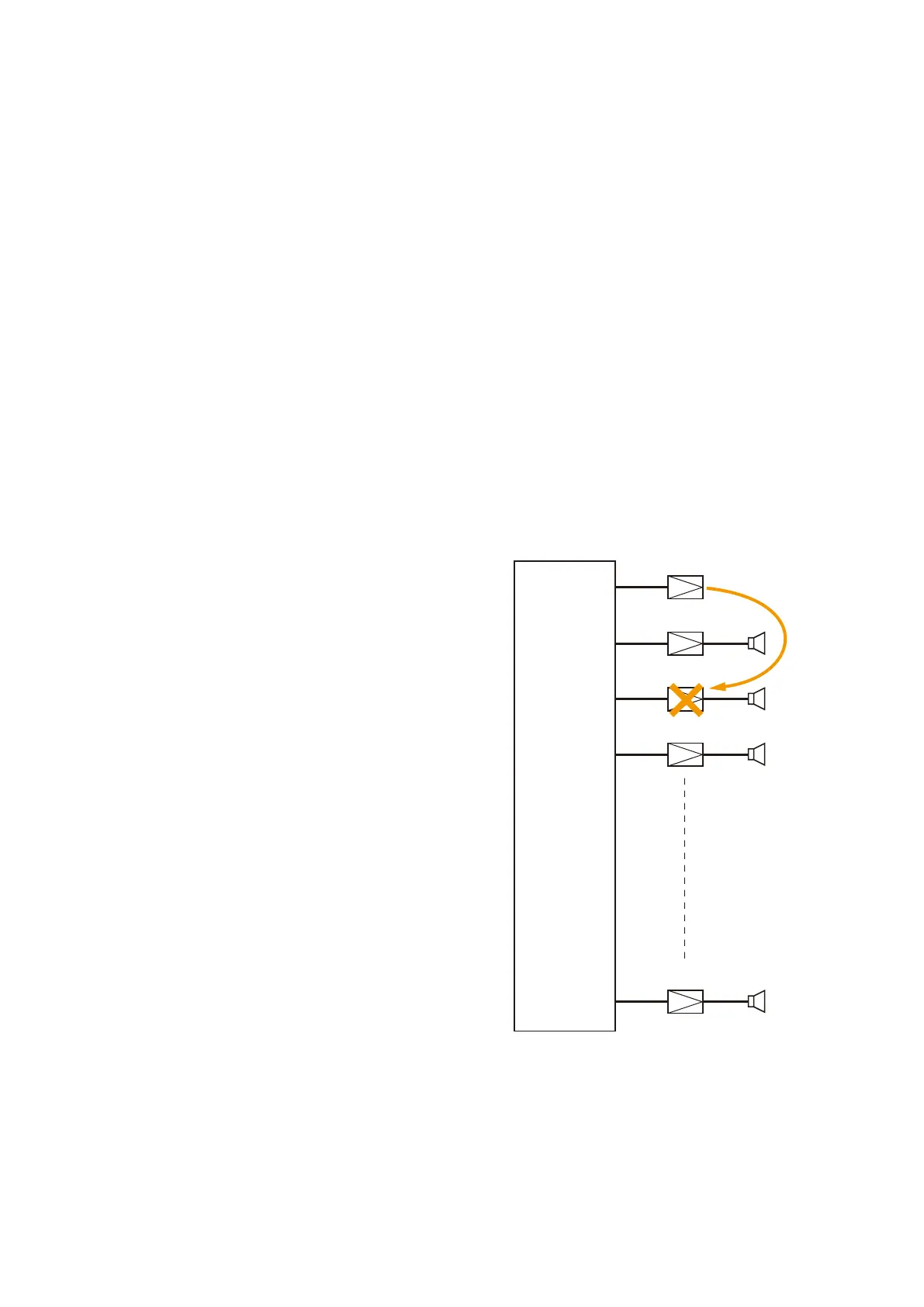
Example
When a failure of Amp 2 is detected, the amplifier is
automatically switched over to the standby amplifier.
In this event, the standby amplifier's CH LED changes
from steady red to steady green conditions.
VX-2000SF
Amp 10
Standby Amplifier
Amp 1
Amp 2
Amp 3