Chapter 2: PRODUCT DESCRIPTIONS
2. NOMENCLATURE AND FUNCTIONS
2-4
2. NOMENCLATURE AND FUNCTIONS
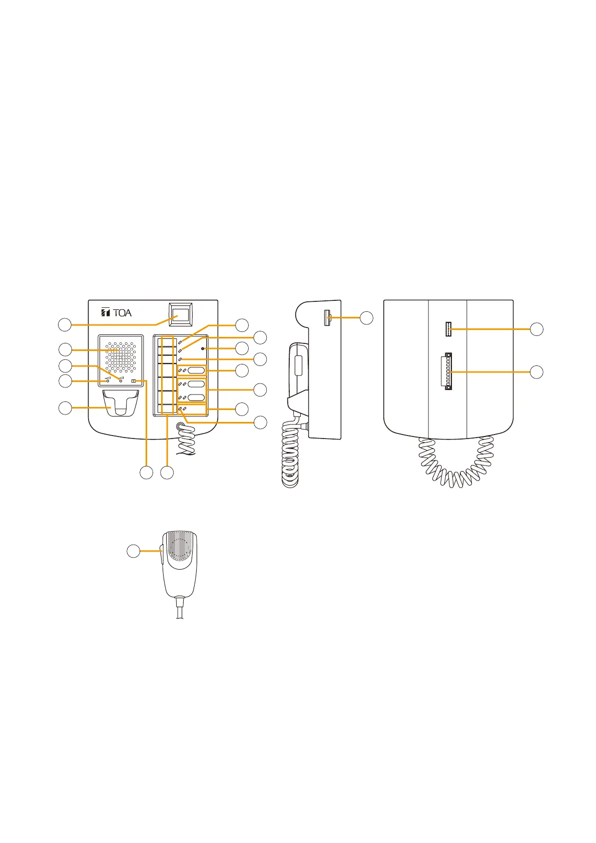
2.1. Fireman's Microphone RM-200XF
EXTENSION
FIREMAN'S MICROPHONE
RM-200XF
MICSP CPU
OFFON
[Top]
[Hand-held microphone]
(Unidirectional type)
[Bottom][Side]
1
2
3
4
15
16
17
5
7
7
6
8
9
10
11
12
13
14
18
• Speciallydesignedforbothemergencyandgeneralpurposebroadcastapplications,theFireman'sMicrophone
can be used for push-button zone selection and microphone broadcasts.
• PC-programmable system software permits desired functions to be assigned to individual Function keys
(equipped with 2 LED indicators).
• Upto10RM-210RemoteMicrophoneExtensionunitscanbeusedwitheachRM-200XFRemoteMicrophone.
• Upto4RM-200XFFireman'sMicrophonescanbeconnectedwithinasystem.
• TheCPUswitchenablesall-zoneemergencybroadcastsfromtheRM-200XFFireman'sMicrophone,even
when the CPU malfunctions.
• FailuresofEmergencybuttonsandsignal(bothcontrolandaudio)pathbetweenthemicrophone(including
the internal microphone element) and the VX-2000 System Manager are automatically detected.
1. Power indicator
Lights green to indicate that the unit is powered
and operational.
Extinguishes when no power is supplied or power
voltage drops below the operational level.
2. Failure indicator
Indicates system operating status.
•Off: Normal
•Lightsyellow: Systemfailuredetected
•
Flashes yellow
:
Communications error detected
between VX-2000 and RM-200XF
•Lightsorflashesgreen:
RM-200XF CPU failure detected
3. Service switch
Used only for service maintenance and for returning
the unit operation to a password entry status (only
when a password is set). Do not touch this switch
for other purposes.
Refer to
p. 7-23 for password setting and p. 5-2
for bringing the unit into password entry status.
4. CPU indicator (Red)
Extinguishes when the CPU switch is set to ON.
Lights red when the CPU switch of any RM-200XF
unit in the system is set to OFF.
5. Function key 2
(with red, green, or orange LED indicators)
Various functions can be assigned to this key using
the PC system setting software.
Refer to p. 7-54 for the assignable functions.
This key can be disabled by the DIP switch No.
17 setting, functioning as an indicator. For details,
refer to
p. 8-5.