Chapter 2: PRODUCT DESCRIPTIONS
2. NOMENCLATURE AND FUNCTIONS
2-16
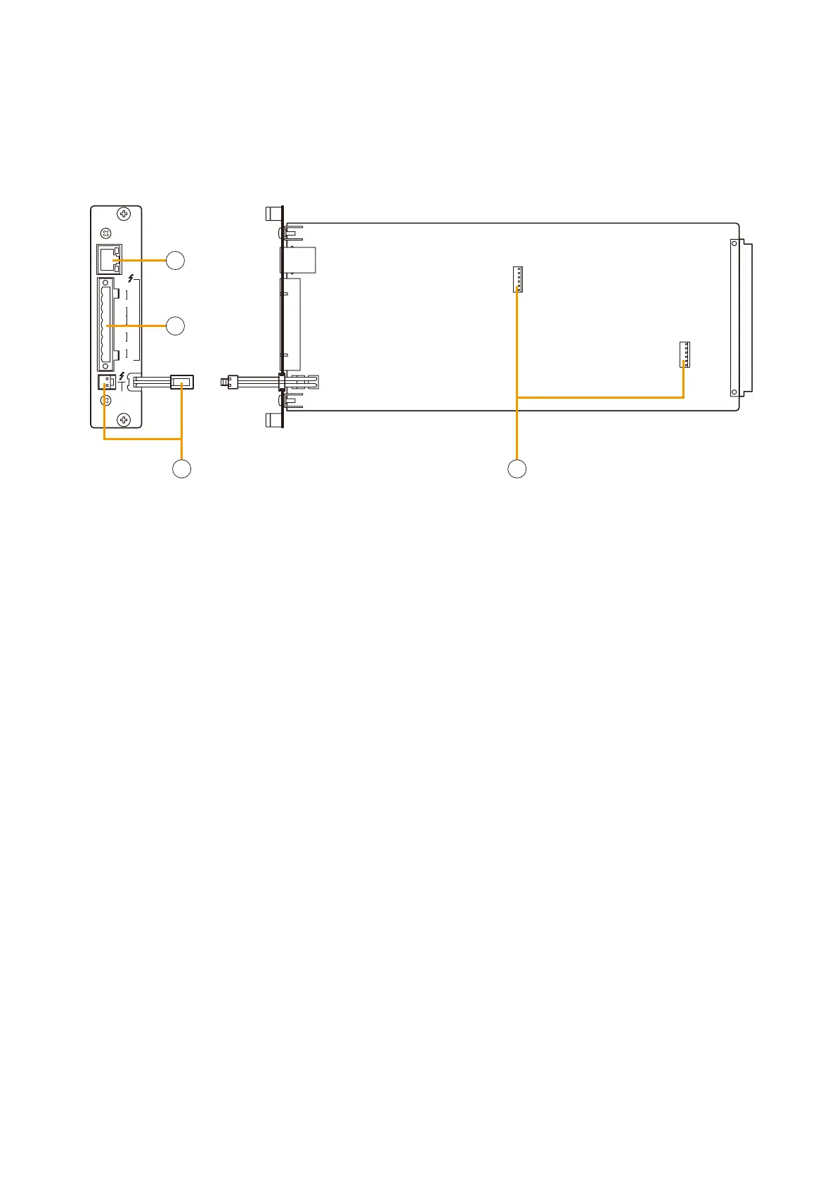
2.9. Pilot Tone Detection Module VX-200SP
STANDBY
PA BUS
VX-200SP
PA
LINK
H
LINE
MONITOR
CH
SP
OUT
CH
PA
IN
CN1 N2C
ATT
CTRL
1
4
3
2
1.Poweramplierlinkconnector[PALINK]
This RJ45 connector connects to the PA LINK
connector of the VP-200VX Power Amplifier Input
module or the VP-3000 series Power Amplifier.
Both LEDs on this connector are not used.
2. VX-200SP plug-in screw connector
Signal lines to be connected are shown below:
•Linemonitorinput[LINEMONITOR]
Monitors connected speaker lines.
Connect by wiring from the speaker line end.
•Externalattenuatorcontrol[ATTCTRL]
Permits connection of a 3- or 4-wire system
attenuator.
For the attenuator connection, refer to
p. 9-7.
•Speakeroutput[SPOUT]
Connects to the speaker.
•Poweramplifierinput[PAIN]
Connects to the power amplifier's speaker
output terminal.
3.Standbyamplierbusconnector
[STANDBY PA BUS]
Connects to all outputs of a single VX-2000SF unit
to be switched over to the standby amplifier when
the power amplifier fails. For details, refer to
p.
9-9, 9-10 for Standby Amplifier Connection.
4. VX-200SE mounting connector
Used to mount the VX-200SE Equaliser Card.
Install this module in the VX-2000SF Surveillance Frame to detect speaker line short circuits, open circuits by
monitoring for the presence of a pilot signal, and ground fault.