Chapter 8: INSTALLATION AND SETTING PROCEDURES (HARDWARE)
2. VX-2000, VX-200XR, VX-200XI, AND EV-200
8-20
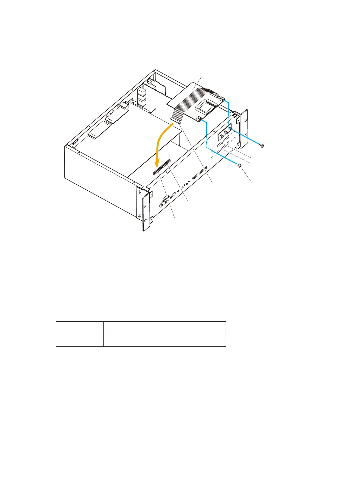
3-1. When using a single EV-200 unit
3-1-1. Using the 2 screws supplied with the EV-200, mount the EV-200 in "Position 1" in the VX-2000.
EV1 CN501
EV-200
EV2 CN502
CN401
Position 1
Position 2
Mounting screw
(supplied with the EV-200)
VX-2000
3-1-2. Plug the EV-200's CN401 connector into the "EV1" connector (CN501) on the VX-2000's circuit
board.
Note: The EV-200 will not operate correctly if the CN401 is plugged into the "EV2" connector
(CN502).
3-2. When using 2 EV-200 units
The mounting position is determined by the type of emergency message recorded on the CF card
mounted in the EV-200.
Perform "Position 2" mounting first, followed by "Position 1".
3-2-1. Using the 2 supplied screws, mount the EV-200 (Evacuation message) in "Position 2" of the
VX-2000. For the mounting method, refer to Step 3-1-1 above.
3-2-2. Plug the CN401 connector from the EV-200 (Evacuation message) into the "EV2" (CN502)
connector on the VX-2000's circuit board.
3-2-3. Mount the EV-200 (Alert message) in "Position 1" of the VX-2000 in the same way as Step 3-2-1
above.
3-2-4. Plug the CN401 connector from the EV-200 (Alert message) into the "EV1" (CN501) connector
on the VX-2000's circuit board.
Step 4. Replace both the top and front panels.
Step 3. Mount the EV-200.
Message Type Mounting Position Connected Connector
Alert “Position 1” (EV1) CN501
Evacuation “Position 2” (EV2) CN502