Chapter 8: INSTALLATION AND SETTING PROCEDURES (HARDWARE)
3. VX-2000SF, VX-200SZ , VX-200SP, VX-200SI , VX-200SO, AND VX-200SE
8-28
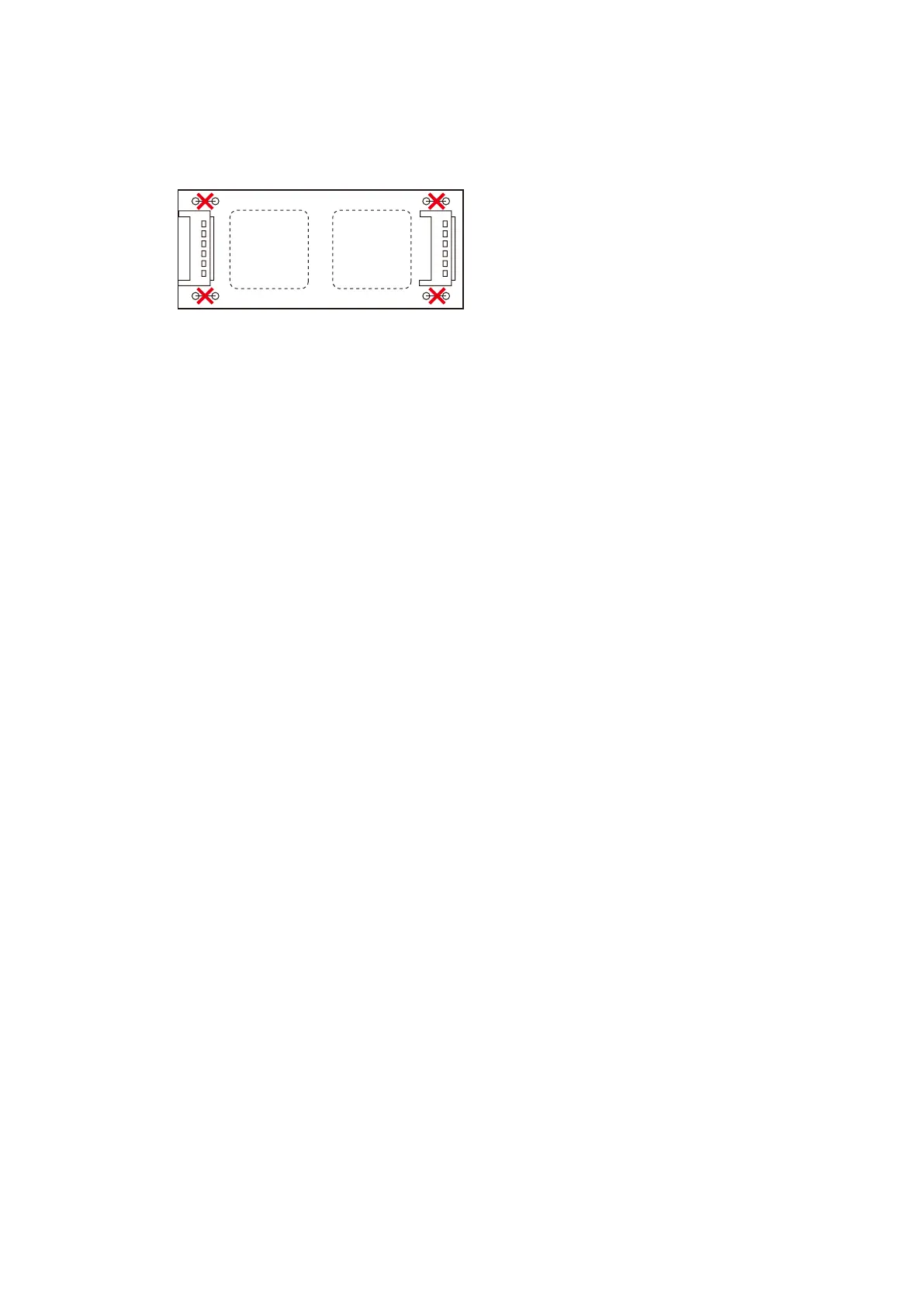
Step 3. Cut the jumper wires installed on each transformer board.
(4 jumpers SJP1401 - SJP1404 on each OT PCB.)
Step 4. Solder the IT-450 transformers to locations T1401 and T1402 on each OT PCB.
Step 5. Fit both OT PCBs back into place.
Step 6. Replace the removed modules and blank panels.
[OT PCB]
T1402 T1401
SJP1403 SJP1401
SJP1404 SJP1402