Chapter 8: INSTALLATION AND SETTING PROCEDURES (HARDWARE)
4. VP-2064, VP-2122, VP-2241 AND VP-2421 POWER AMPLIFIERS
8-35
[Channel-to-connector relationship]
Step 3. Change wiring.
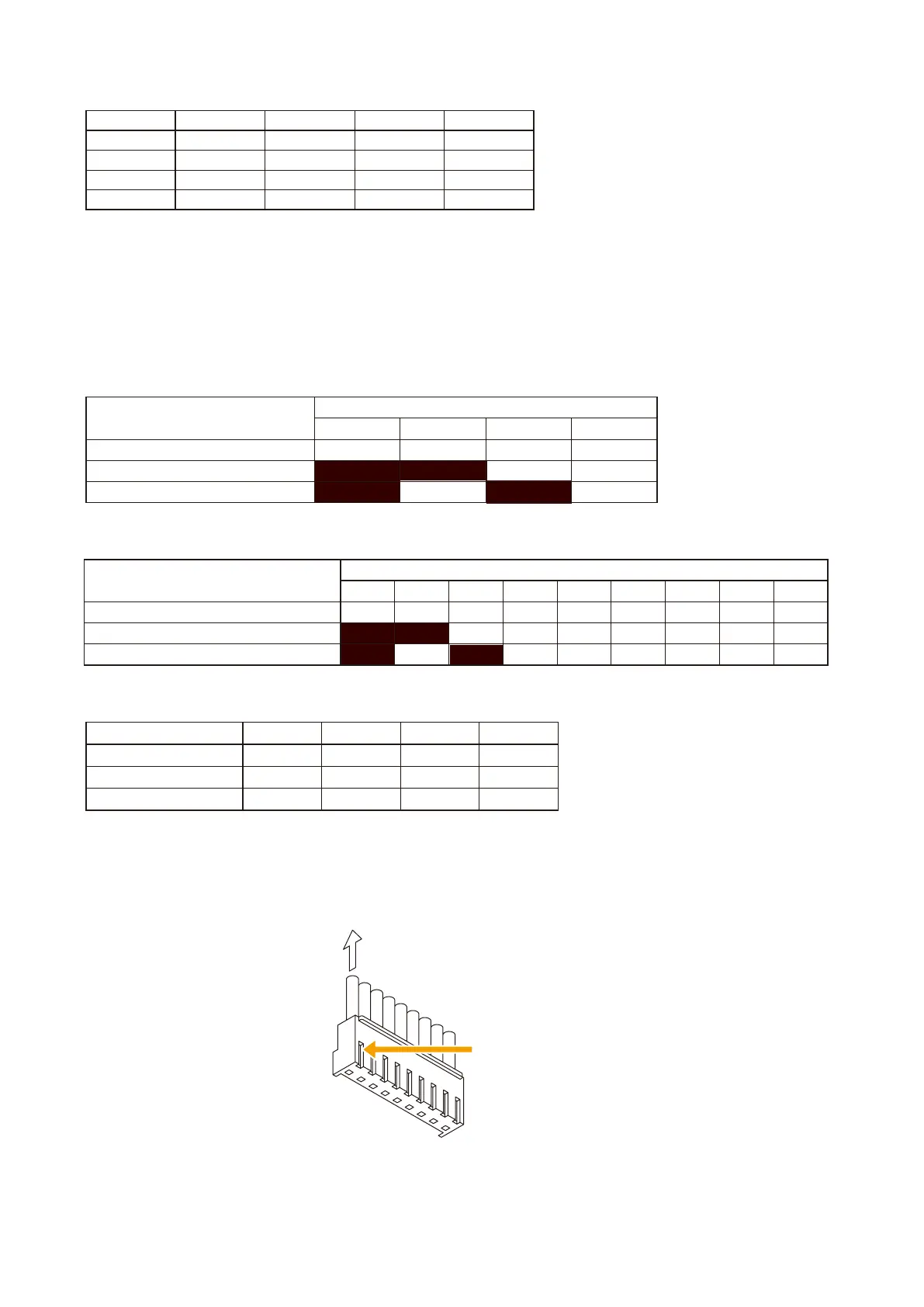
Disconnect a line and exchange it with the corresponding line. Refer to the figure below when removing.
To change to 50 V, exchange the Pin No. 1 line (white) with the Pin No. 3 line (blue).
To change to 70 V, exchange the Pin No. 1 line (white) with the Pin No. 2 line (purple).
[VP-2064/VP-2421 Connector Pin Assignment]
[VP-2122/VP-2241 Connector Pin Assignment]
[Speaker line voltage/impedance]
Pull out the cable.
Press the lock spring.
1
9
[How to remove cables from connector]
Pull out the cable pressing the lock spring with a pointed object like tweezers as shown below.
Step 4. Insert the connectors back into their original positions on the circuit board.
Step 5. Replace the top panel.
Model No. VP-2064 VP-2122 VP-2241 VP-2421
Channel 1 CN102 CN102 CN102 CN102
Channel 2 CN202 CN202
- -
Channel 3 CN302
- - -
Channel 4 CN402
- - -
Speaker line voltage
Pin No.
1 2 3 4
100 V (factory-preset voltage) White Purple Blue Black
70 V Purple White Blue Black
50 V Blue Purple White Black
Speaker line voltage
Pin No.
1 2 3 4 5 6 7 8 9
100 V (factory-preset voltage) White Purple Blue Green Yellow
Orange
Red Brown Black
70 V Purple White Blue Green Yellow
Orange
Red Brown Black
50 V Blue Purple White Green Yellow
Orange
Red Brown Black
Speaker line voltage VP-2064 VP-2122 VP-2241 VP-2421
100 V 167Ω 83Ω 41Ω 24Ω
70 V 83Ω 41Ω 21Ω 12Ω
50 V 41Ω 21Ω 10Ω 6Ω