Chapter 8: INSTALLATION AND SETTING PROCEDURES (HARDWARE)
4. VP-2064, VP-2122, VP-2241 AND VP-2421 POWER AMPLIFIERS
8-37
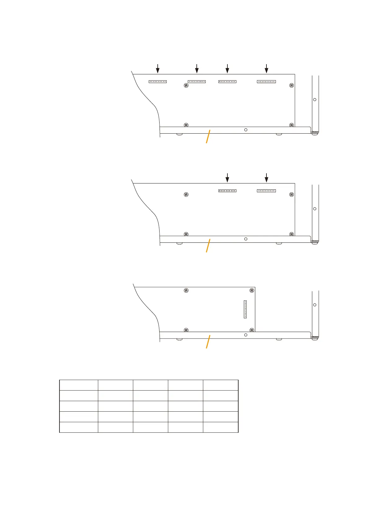
Step 4. Plug the VP-200VX's connector into the corresponding channel connector on the circuit board inside
theamplier.
[VP-2064 Connector position]
Rear panel
CN106
CH1
CN206
CH2
CN306
CH3
CN406
CH4
DRIVE PCB
[VP-2122 Connector position]
[VP-2241/-2421 Connector position]
Rear panel
Rear panel
CN106
CH1
CN206
CH2
DRIVE PCB
DRIVE PCB
CN106
[Channel-to-connector relationship]
Step 5. After mounting is completed for all required channels, replace the top panel.
Model No. VP-2064 VP-2122 VP-2241 VP-2421
Channel 1 CN106 CN106 CN106 CN106
Channel 2 CN206 CN206
- -
Channel 3 CN306
- - -
Channel 4 CN406
- - -