Chapter 9: CONNECTIONS
6. CONNECTION CABLE PIN ASSIGNMENT
9-26
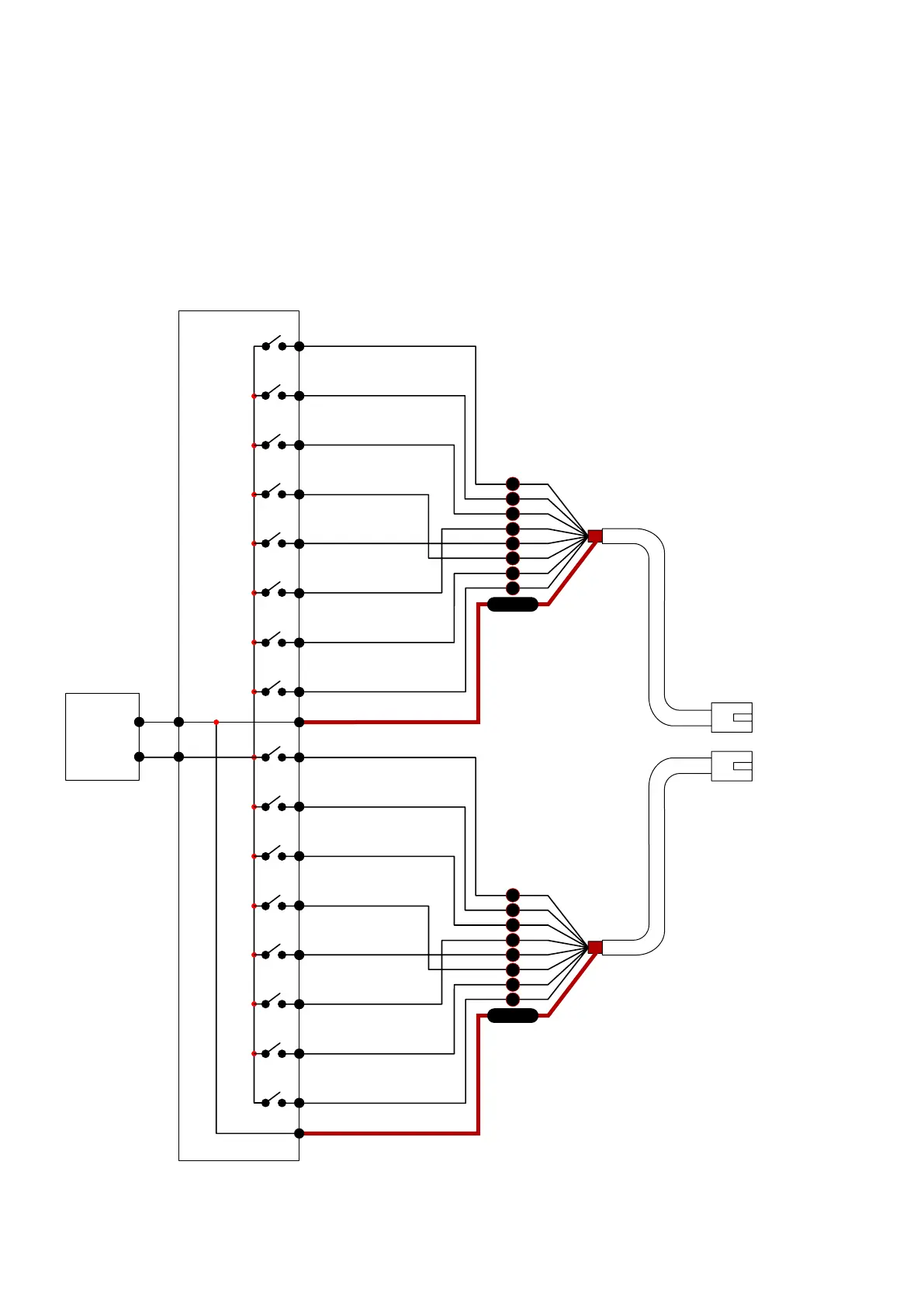
[VX-2000 Control input insulation]
Because the VX-2000's control input uses photocouplers, it can be insulated by performing settings to be
externally powered.
This setting disconnects both CTRL IN 1 – 8 Common terminal and CTRL IN 9 – 16 Common terminal from the
VX-2000's internal GND terminal, changing them to external power supply terminals. (Refer to
p. 8-17 for the
setting procedure.)
To VX-2000 CTRL IN
RJ45 connector
Pin No.
1
2
5
4
3
6
7
8
Shield
1 – 8
CTRL IN 1
CTRL IN 2
CTRL IN 3
CTRL IN 4
CTRL IN 5
CTRL IN 6
CTRL IN 7
CTRL IN 8
CTRL IN 1 – 8 Common
1
2
3
4
5
6
7
8
9
10
11
12
13
14
15
16
CTRL IN 9
CTRL IN 10
CTRL IN 11
CTRL IN 12
CTRL IN 13
CTRL IN 14
CTRL IN 15
CTRL IN 16
CTRL IN 9 – 16 Common
RJ45 connector
Pin No.
1
2
5
4
3
6
7
8
Shield
9 – 16
VX-2000 Control Input (photocoupler-insulated)
Electrical characteristics
Voltage requirement: 17 – 24 V DC
Short circuit current: Under 7 mA
Control current: 5 – 7 mA
+
-
DC
17 – 24 V
External
power supply
•Connectionexample