3–1
Chapter 3. REAR PANEL
CONNECTORS
AND PINOUTS
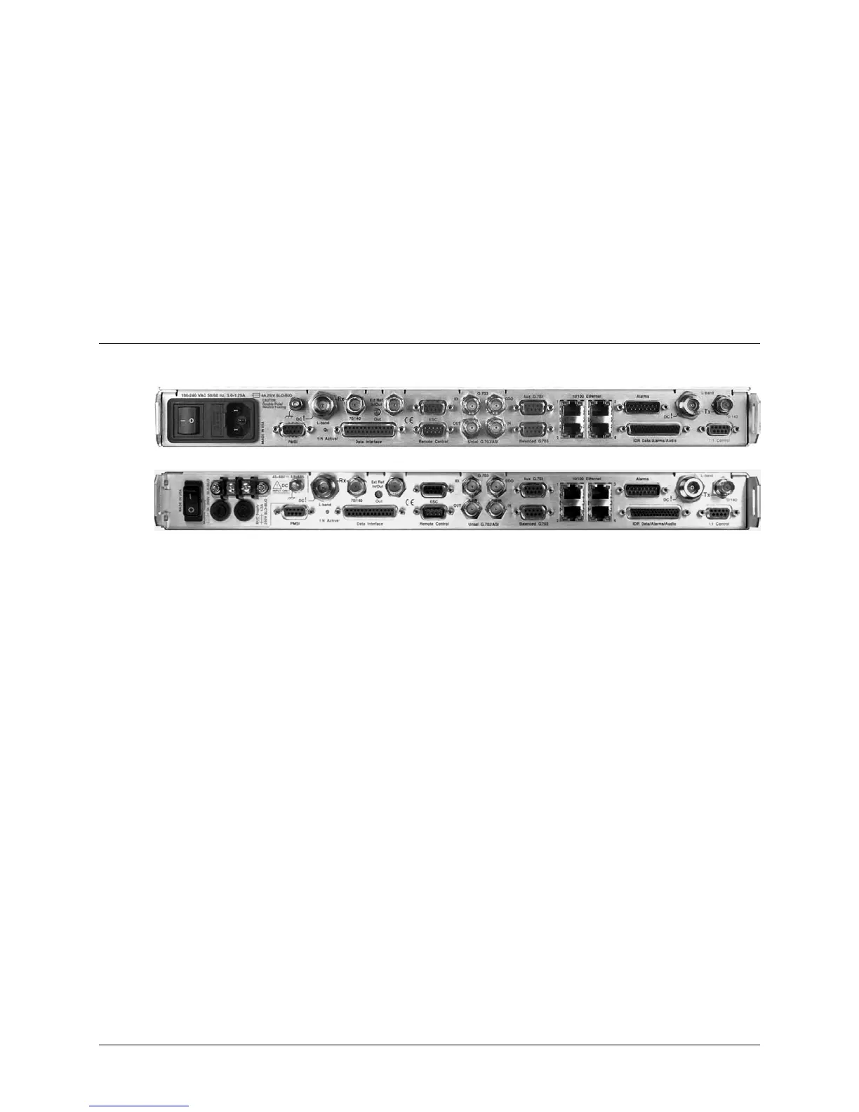
3.1 CDM-625 Rear Panel Overview
Figure 3-1. CDM-625 Rear Panel View
(Top) Standard AC Chassis (CEFD P/N PL/12587-1)
(Bottom) Optional 48V DC Chassis (CEFD P/N PL/12587-2)
The CDM-625 Advanced Satellite Modem’s rear panel, shown in Figure 3-1, provides all
necessary external connections between the modem and other equipment:
• Section 3.2 details the cabling connections provided on the rear panel interface,
grouped according to service function. Where applicable, the connector’s pinout table is
provided.
• Section 3.3 details the CDM-625 grounding and power features.