CDM-625 Advanced Satellite Modem Revision 13
Rear Panel Connectors and Pinouts MN-CDM625
3–2
3.2 CDM-625 Cable Connections
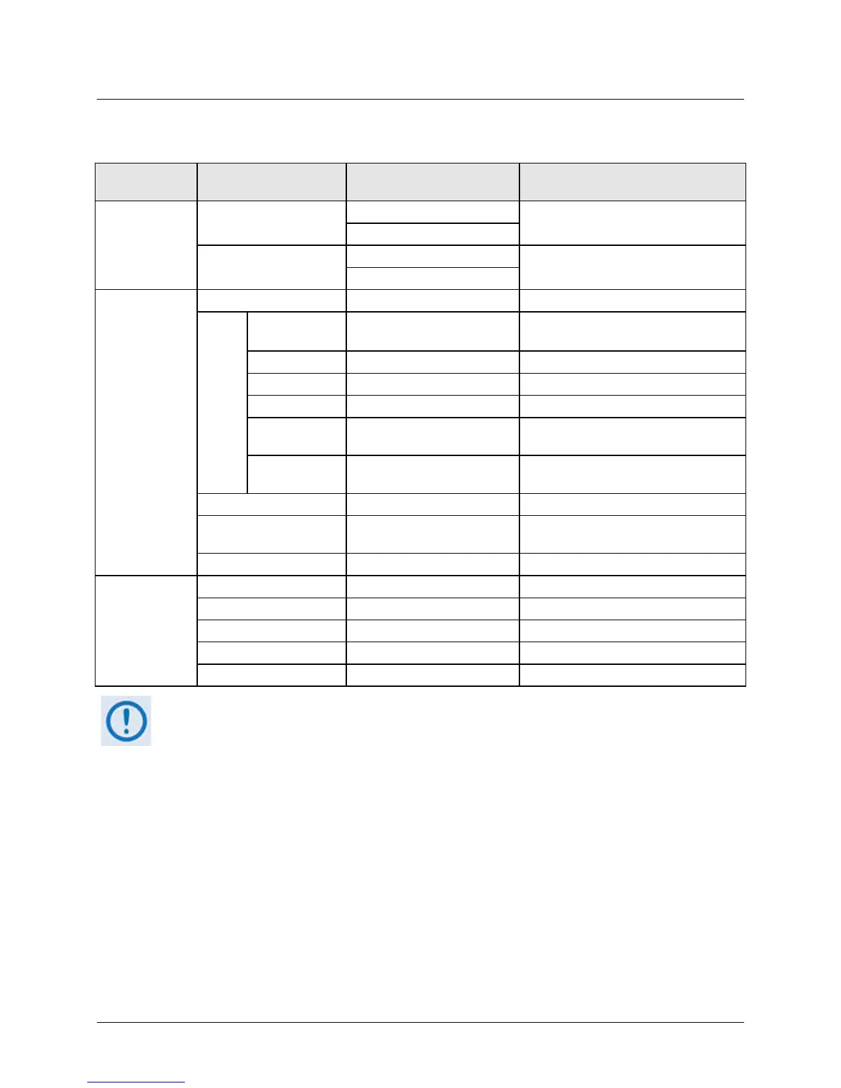
Table 3-1. CDM-625 Rear Panel Cabling Connections
Name Connector Type Function
Sect. 3.2.1
Rx
BNC female (70/140MHz band)
IF Input
Tx
BNC female (70/140MHz band)
IF Output
Sect. 3.2.2
Serial synchronous data input/output
G.703
Data
Balanced G.703 9-pin Type ‘D’ female
G.703, D&I or D&I++;
Quad E1 Ports 1 & 2
IDI BNC female
Insert Data In / Sub-rate Auxiliary Tx
DDO BNC female
Drop Data Output / Sub-rate Auxiliary Rx
G.703 Out
10/100 Base-T management and data
IDR Data/Alarms/Audio
44-pin High Density Type ‘D’
female
Intelsat Open Network auxiliary signals
ESC Input/output (RS232/485)
Sect. 3.2.3
Remote Control 9-pin Type ‘D’ male Serial Remote Interface (RS232/485)
Form C Alarms (relay closures)
Pre-Mapped Symbol Interface (CnC)
Connection to External 1:1 Controller
The European EMC Directive 2004/108/EEC (EN 55022, EN 50024) requires using properly
shielded cables for DATA I/O. These cables must be double-shielded from end-to-end,
ensuring a continuous ground shield.