CDM-625 Advanced Satellite Modem Revision 13
Rear Panel Connectors and Pinouts MN-CDM625
3–4
3.2.2 Terrestrial Data Connection Group
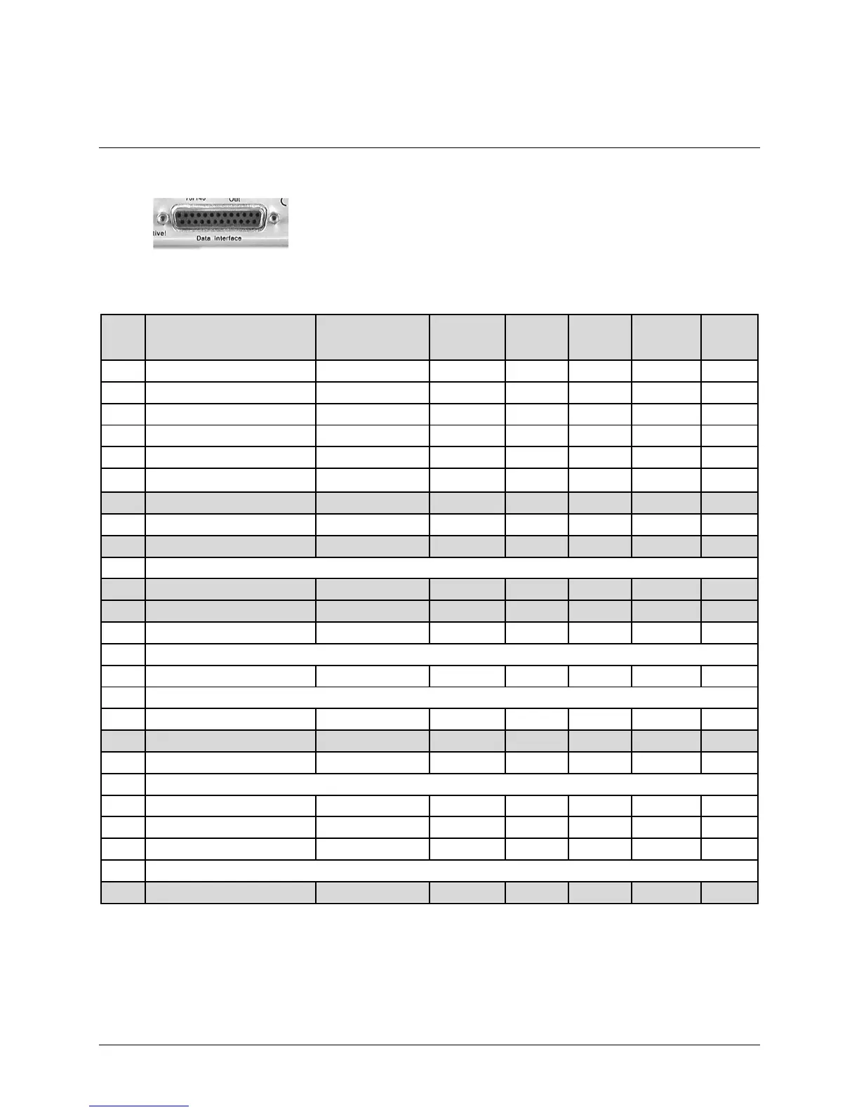
3.2.2.1 Data Interface (DB-25F)
The Data Interface connector is a 25-pin, Type ‘D’ female interface that
conducts data input and output signals to and from the modem, and
connects to customer’s terrestrial equipment, breakout panel, or
protection switch.
Table 3-2. Data Interface Connector Pinouts
Pin #
(R-L)
Generic Signal Description Direction
EIA-422
EIA 530
V.35 HSSI LVDS
Circuit
#
1 Shield – Shield FG Shield Shield 101
14 Transmit Data B DTE to Modem SD B SD B SD B SD B 103
2 Transmit Data A DTE to Modem SD A SD A SD A SD A 103
15 Internal Transmit Clock A Modem to DTE ST A SCT A ST A ST A 114
3 Receive Data A Modem to DTE RD A RD A RD A RD A 104
16 Receive Data B Modem to DTE RD B RD B RD B RD B 104
4 Request to Send A * DTE to Modem RS A RTS TA A – 105
17 Receive Clock A Modem to DTE RT A SCR A RT A RT A 115
5 Clear to Send A * Modem to DTE CS A CTS – – 106
18 (NOTE 2)
6 Data Set Ready A (NOTE 2) Modem to DTE DM A DSR – – –
19 Request to Send B * DTE to Modem RS B - TA B – 105
7 Signal Ground – SG SG SG SG 102
20 (NOTE 2)
8 Receiver Ready A Modem to DTE RR A RLSD CA A RR A 109
21 (NOTE 2)
9 Receive Clock B Modem to DTE RT B SCR B RT B RT B 115
22 Data Set Ready B (NOTE 2) Modem to DTE DM B – – – –
10 Receiver Ready B Modem to DTE RR B – CA B RR B 109
23 (NOTE 2)
11 Transmit Clock B DTE to Modem TT B SCTE B TT B TT B 113
24 Transmit Clock A DTE to Modem TT A SCTE A TT A TT A 113
12 Internal Transmit Clock B Modem to DTE ST B SCT B ST B ST B 114
25 (NOTE 2)
13 Clear to Send B * Modem to DTE CS B – – – 106
Notes:
1. When the r ear-panel LE D m arked “1:N A ctive!” i s OFF, al l of t he s ignals s hown abov e ar e av ailable and f unctional. I n
addition, pi ns not s hown are not connected, and therefore no damage will oc cur i f ot her signals ar e c onnected to the
additional pins.