CDM-625 Advanced Satellite Modem Revision 13
Rear Panel Connectors and Pinouts MN-CDM625
3–13
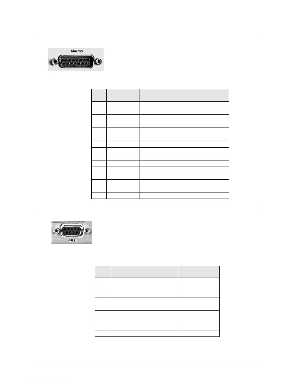
3.2.3.2 Alarms (DB-15M)
Unit alarms are provided on this 15-pin Type ‘D’ male connector.
Table 3-12. Alarm Interface Connector Pinouts
Name Signal Function
1 GND Ground
9 EXT-OFF EXT Carrier OFF
AGC Voltage (Rx signal level, 0 to 10 Volts)
3 RX-Q Rx Q Channel (Constellation Monitor)
RX I Channel (Constellation Monitor)
Unit Fault (Energized, No Fault)
5 UNIT-NC Unit Fault (De-energized, No Fault)
Tx Traffic (Energized, No Fault)
Tx Traffic (De-energized, No Fault)
Rx Traffic (Energized, No Fault)
Rx Traffic (De-energized, No Fault)
3.2.3.3 PMSI Connector, DB-9F
The PMSI (Pre-Mapped Symbol interface) is a 9-pin Type ‘D’ female
connector. The PMSI is an EIA-485 multidrop bus system, used in tandem
with Carrier-in-Carrier (CnC), where one device transmits, and all other
devices on the multidrop bus are configured to receive.
Table 3-13. PMSI (Pre-Mapped Symbol Interface) Connector Pinouts
Description Direction
PMSI symbol clock – RS485 -
PMSI symbol clock – RS485 +