TRANSPONDER KEY
DESCRIPTION
The Sent ry Key Immobilizer System (SKIS) which
communicat es wit h the Sentry Key Rem ote Entr y
Module (SKREEM), uses a tr ansponder ch ip tha t is
integra l t o ea ch key fob (Fig. 6). Ignit ion keys are
su pplied wit h the vehicle wh en it is shipped fr om the
factory. The tra nsponder ch ip is loca ted with in the
Remote Keyless Ent ry (RKE) fob.
OPERATION
Each Sentry Key has a un ique transponder iden ti-
ficat ion code permanently progr amm ed into it by th e
manufactu rer. Likewise, t he Sentry Key Remot e
Entry Module (SKREEM) has a unique “Secret Key$
code program med into it by th e m anufactur er as
well. When a Sen try Key is progr ammed into the
memor y of the SKREE M, the SKRE EM st ores the
transpon der identification code from the Sen try Key,
and t he Sen try Key lear ns the “Secr et Key” code
from the SKREE M. Once the Sentry Key learns the
“Secret Key” code of the SKREEM, it is also perma-
nent ly program med in to th e tra nsponder’s memory.
The Sentry Key’s transponder is within the range
of the SKREEM’s transpon der ring when it is
inser ted in to the ign ition lock cylinder. When the
ign ition switch is turned to the ON position, the
SKREEM communicat es with the Sen try Key via a
radio frequency (RF) signa l. The SKREEM deter-
mines if a valid key is present based on th e informa-
tion it receives fr om the Sen try Key. If a va lid key is
detected, that fact is commu nica ted to t he En gine
Contr ol Module (ECM) via t he Con troller Ar ea Net-
work (CAN) da ta bus and the vehicle is allowed to
continue runn ing. If an invalid key is received by th e
ECM or no stat us at a ll is commu nicated, the vehicle
will sta ll after two (2) seconds of runnin g. Th e indi-
cator light will be fla sh ing a t this poin t. The Sen try
Key’s transponder can not be repa ired. If it is fau lty
or da maged, it mu st be replaced.
Common communication pr oblem s:
• Two tr ansponder keys too close together.
• Speed P ass too close to t ransponder key.
Solid indicator tha t there is a system failure.
• Loss of ECM comm unication.
• Failed tr ansponder ring circu it.
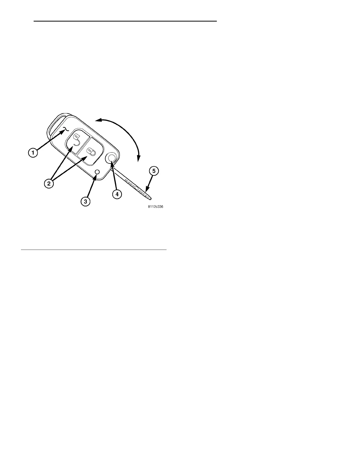
Fig. 6 TRANSPONDER KEY
1 - TRANSPONDER KEY FOB
2 - RKE BUTTONS
3 - INDICATOR LIGHT
4 - KEY BLADE RELEASE BUTTON
5 - KEY BLADE
VA VEHICLE THEFT SECURITY 8Q - 5