(8) In st all th e exhaust han ger fastener s at the
muffler.
(9) Tighten the exhaust han ger bracket to engine
block.
(10) Install the turbocharger support bracket.
(11) Lower th e vehicle.
(12) Install t he air clean er duct to th e tu rbo-
charger (Fig. 71).
(13) Install the exh aust heat shield.
(14) Connect t he negat ive batt ery cable.
TIMING CHAIN COVER
REMOVAL
WARNING: DO NOT OPEN COOLING SYSTEM
UNLESS TEMPERATURE IS BELOW 90°C (194°F).
OPEN CAP SLOWLY TO RELEASE PRESSURE.
STORE COOLANT IN APPROVED CONTAINER
ONLY. RISK OF INJURY TO SKIN AND EYES FROM
SCALDING COOLANT. WEAR PROTECTIVE
GLOVES, CLOTHING AND EYE WEAR.
(1) Disconn ect nega tive battery cable.
NOTE: Rotate engine on crankshaft. DO NOT crank
the engine at the bolt of the camshaft sprocket.
NOTE: DO NOT crank engine back.
(2) Position piston of cylin der 1 to ignition TDC.
Mar kin gs on the camshaf t b e ar ing cap must be
aligned.
(3) Drain coolant (Refer to 7 - COOLING/E NGINE/
COOLANT - STANDARD P ROCEDURE).
(4) In st all retaining lock for cr ankshaft /st arter
ring gear (Refer to 9 - ENGINE/ENGINE BLOCK/
FLEX PLATE - INSTALLATION).
(5) Drain engine oil.
(6) Remove the oil filt er to allow the oil t o flow off
into the oil pa n.
(7) Remove the r adiator assembly (Refer to 7 -
COOLING/ENGINE/RADIATOR - RE MOVAL).
(8) Remove engine cover (Refer to9-ENGINE-
REMOVAL).
(9) Remove front cover a t cylinder h ead (Refer to 9
- ENGINE /CYLINDER H EAD - RE MOVAL).
(10) Remove accessor y drive belt.
(11) Remove the high pressur e fuel pum p (Refer to
14 - F UEL SYSTE M/FUEL DELIVE RY/FUE L PUMP
- REMOVAL).
(12) Remove wat er pump (Refer to7-COOLING/
ENGINE/WATER P UMP - REMOVAL).
(13) Remove a ccessor y dr ive belt pu lley a nd vibra-
tion da mper (Refer t o 9 - E NGINE/ENGINE BLOCK/
VIBRATION DAMPER - REMOVAL).
(14) Remove th e power steer ing pump.
NOTE: NO NOT open the air conditioning system.
(15) Un plug AC compr essor electrical connector
and u nbolt AC compr essor. Reloca te in lower engine
compart ment with out opening the system.
(16) Remove the gener ator wit h wiring a tta ched
and relocate som ewher e in th e engine compar tment.
(17) Install en gine su ppor t fixtu re.
(18) Remove th e oil pa n.
(19) Deta ch th e coolant hose to oil-wat er heat
excha nger a t crankcase (F ig. 73).
(20) Remove the cylinder head to timing cov er
bolts (F ig. 73).
(21) Remove the tim ing cover bolts and cover (Fig.
73).
(22) Remove remaining ancillary components
attached to the t iming case cover (Fig. 73).
NOTE: Inspect condition of hoses and clamps,
replace as necessary.
(23) Remove timing cha in tension er (Refer to 9 -
ENGINE/VALVE TIMING/TIMING BE LT/CHAIN
AND SPROCKETS - REMOVAL)
(24) Remove timing ca se cover (Fig. 73).
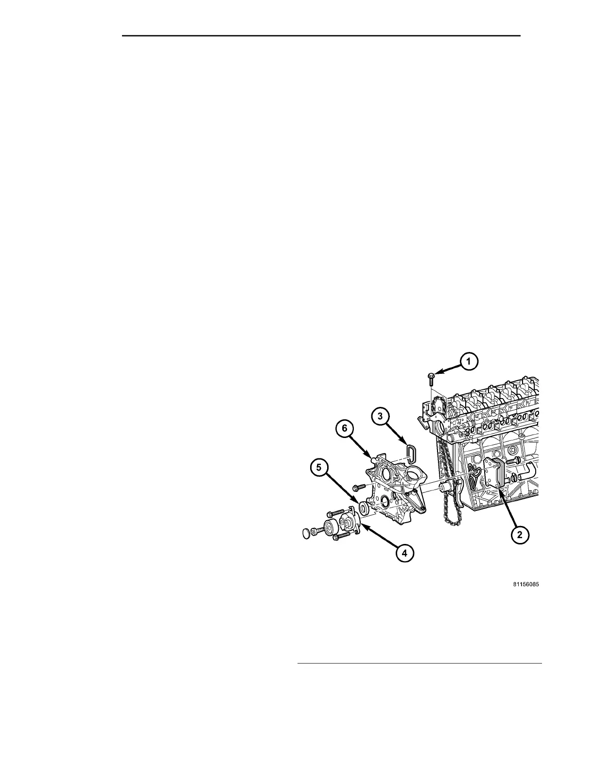
Fig. 73 TIMING CHAIN COVER
1 - CYLINDER HEAD TO TIMING COVER BOLT
2 - OIL-WATER HEAT EXCHANGER
3 - GASKET
4 - DRIVE BELT TENSIONER
5 - FRONT CRANKSHAFT SEAL
6 - TIMING CHAIN COVER
9 - 70 ENGINE VA