(6) Working from the underside of t he switch , gen-
tly r ock the swit ch back and forth out of it s mounting
locat ion in th e switch bezel.
INSTALLATION
(1) In st all the hea ted seat switch in its moun tin g
locat ion in th e switch bezel.
(2) Connect electrical connections.
(3) Position the switch bezel an d in st all the retain-
ing screw. Refer to the Body sect ion for th e proce-
dure.
(4) In st all the storage bin. Refer t o the Body sec-
tion for th e procedur e.
(5) In st all th e gea r selector bezel trim . Refer t o th e
Body section for the pr ocedure.
(6) Connect the n egat ive batt ery cable.
HEATED SEAT ELEMENT
DESCRIPTION
The heat ed seat system includes two sea t hea ting
elements in each fron t sea t, one for the sea t cush ion
(Fig. 1) an d the other for the seat ba ck. All models
use t wo r esistor wire heating elements for ea ch seat
that a re conn ected in series with t he Heated Seat
Relay. The tem per ature sensor is a Negative Temper-
ature Coefficient (NTC) thermistor. On e t empera ture
sensor is u sed for each seat, and it is locat ed in t he
seat cushion hea ting element for all models.
The seat hea tin g elemen ts ar e glued onto t he sea t
and seat back cushions. The heated seat element s
and t he temper ature sensor cann ot be adjusted or
repaired and, if fault y or da maged a new seat a ssem -
bly m u st be in st a lled.
OPERATION
The h eated seat elemen ts resist th e flow of electri-
cal cur rent . When battery cu rren t is passed th rough
the elem ents, the ener gy lost by th e resistance of the
elements is released in t he form of heat. The hea ted
seat tem perature sensor is a NTC thermistor. When
the tem perature of the seat cushion cover rises, th e
resistance of the sensor decrea ses. The heat ed seat
rela y uses t his t empera ture sen sor input to monitor
the tempera ture of the seat , and regula tes the cur-
rent flow to the sea t heat ing elem ents a ccordingly.
DIAGNOSIS AND TESTING - HEATED SEAT
ELEMENT
For complete circuit diagram s, refer to Wi r i n g .
NOTE: When checking heated seat elements for
continuity, be certain to move the heating element
being checked. Moving the element, such as sitting
in the seat will eliminate the possibility of an inter-
mittent open in the element which would only be
evident if the element was in a certain position.
Failure to check the element in various positions
could result in an incomplete test.
(1) Disconn ect and isolate the battery nega tive
cable. Discon nect the h eated seat element wire ha r-
ness con nector from under the seat cushion. Check
for continuity bet ween the sea t hea ter driver circuit
and groun d. There should be continuity, less than 7
ohms. If OK, go to Step 2. If not OK, replace th e sea t
assembly.
(2) Check for continu ity between the seat heater
B+ driver circuit cavity a nd the sea t back frame.
There should be no continu ity. If OK, heating ele-
ment is OK at t his time. If n ot OK, replace t he seat
assembly.
HEATED SEAT RELAY
DESCRIPTION
The heated sea t relay is an electr omecha nica l
device tha t switches 12v ba tter y curren t to t he
heat ed sea t element s when t he relay control coil is
energized. The heat ed seat relay is loca ted in th e
Fuse Block, under t he dr iver s sea t. Th e heated sea t
rela y is a In tern ational St andards Or ganizat ion
(ISO) r elay. Relays conforming t o the ISO specifica-
tions h ave common physical dimensions, curren t
capacities, ter mina l pa tterns, an d term inal fun ctions.
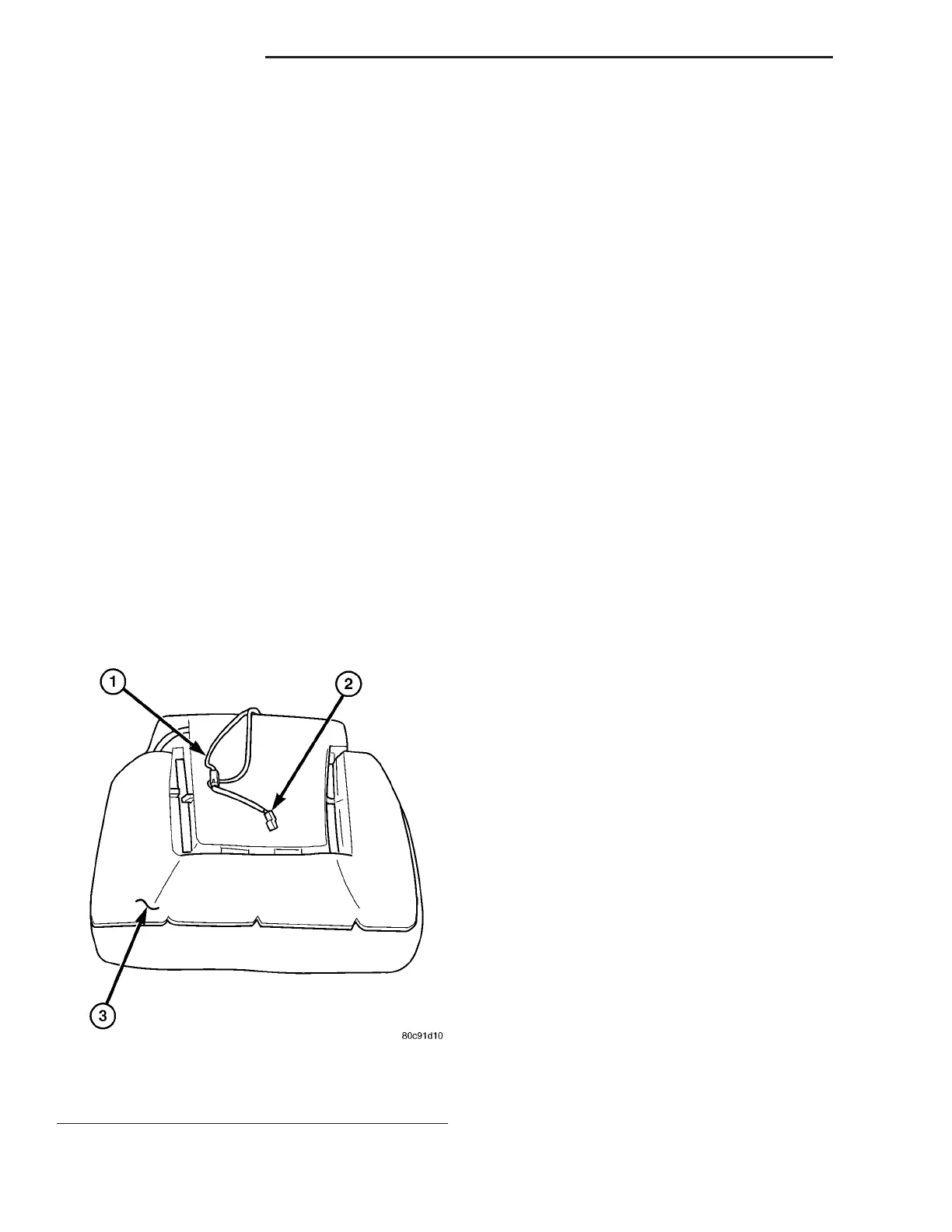
Fig. 1 Heated Seat Element - Typical
1 - Seat Back Wire Harness
2 - Heated Seat Wire Harness Connector
3 - Heated Seat Cushion Element
8G - 12 H EAT ED S EAT S VA