The heated seat system components opera te on
batt ery cur rent received th rough a fuse in the Fuse
Block on a fused ign ition switch output (run-acc) cir-
cuit so that the system will only operate when the
ign ition switch is in t he On or Accessory posit ions.
The hea ted seat system will be turned Off au toma ti-
cally whenever the ignition switch is t urned to an y
position except On or Accessory. Also, the heat ed sea t
system will not oper ate wh en the surface temper a-
ture of the seat cushion cover at eith er heat ed sea t
sensor is above the designed temper ature set points
of the system .
DIAGNOSIS AND TESTING - HEATED SEATS
Refer t o Wi r i n g for th e appropriate wiring infor-
mation. Th e wiring inform ation inclu des wiring dia-
gra ms, pr oper wire and con nector repair procedu res,
further details on wire harn ess routing and reten -
tion, as well as pin-out and loca tion views for the
var ious wire ha rness connectors, splices an d grounds.
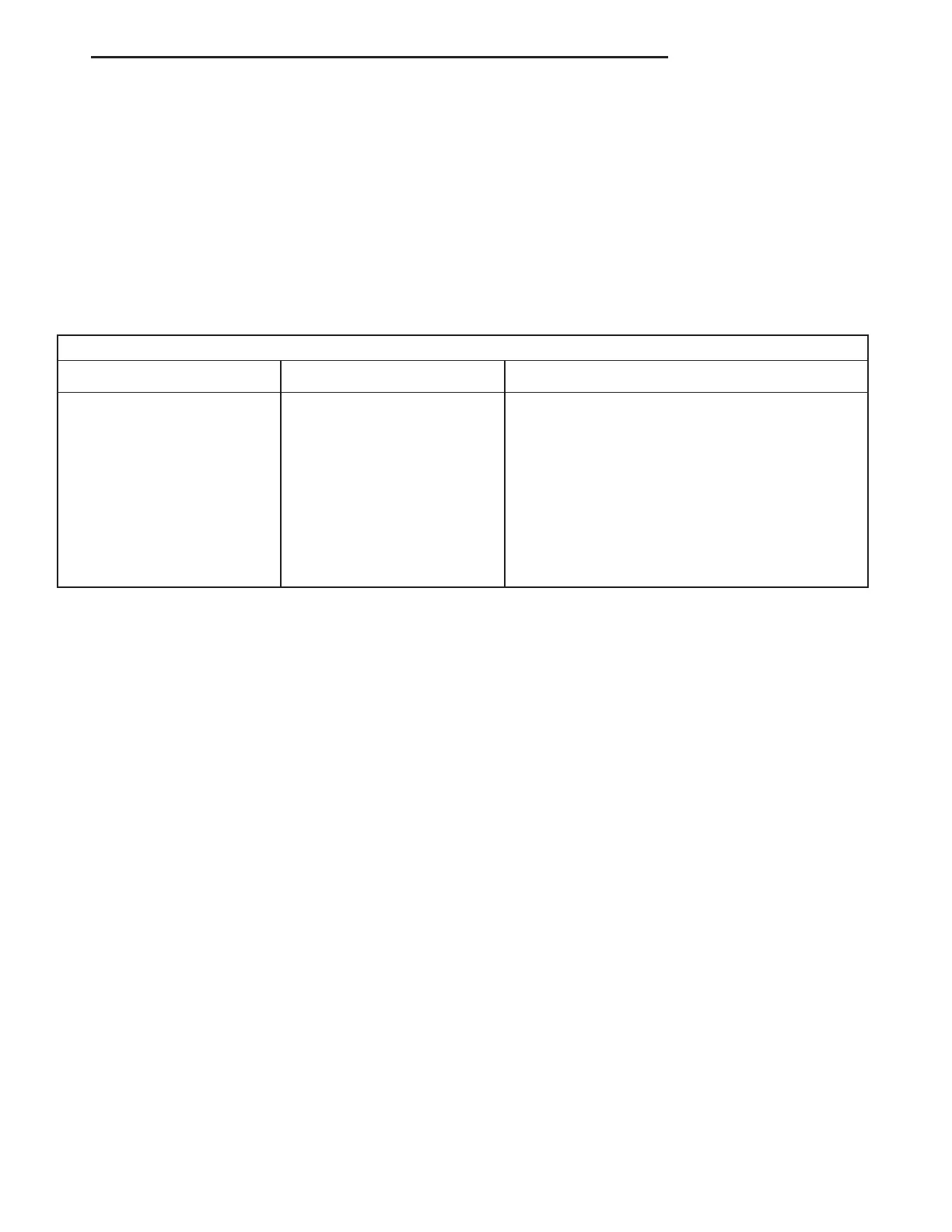
HEATED SEAT SYSTEM DIAGNOSIS
CONDITION POSSIBLE CAUSES CORRECTION
NO HEATED SEAT SWITCH
ILLUMINATION WITH IGNI-
TION ON
1. Faulty fuse. 1. Check heated seat fuse in Fuse Block. Re-
place fuse, if required.
2. Wiring faulty. 2. Check fused ignition switch output (run-acc)
circuit from heated seat switch connector to igni-
tion switch. Repair, if required.
3. Ground faulty. 3. Check for ground at heated seat switch con-
nector. Repair, if required.
4. Faulty switch. 4. Refer to Heated Seat Switch for the proper
switch diagnosis and testing procedures.
DRI V ER H EAT ED SEAT
SWI T CH
DESCRIPTION
The hea ted seat switches are loca ted on the instr u-
ment pa nel, in th e accessory switch bezel. The t wo,
momen tary rocker type switch es pr ovide a signal to
the Heated Sea t Rela y t hrough separate ha rd wir ed
circuits. Each swit ch con tains two ligh t emit ting
diodes (LED), one for ea ch High and Low setting t o
let th e occupan t kn ow that th e seat heater system is
on.
The hea ted sea t switches an d their LED’s ca nnot
be repa ired. If either switch is faulty or dama ged th e
entire switch mu st be replaced.
OPERATION
There are three modes that can be selected with
each of the heated seat swit ches: Off, Low, and High.
When the top of th e switch rocker is depr essed, t he
low mode is select ed and the low mode LE D in dicator
illuminates. Depressing the top of th e switch rocker a
second time will t urn the hea ted sea t to Off. This
sa me pr ocess is r epeated for High heat setting. The
heat ed seat s will automa tically r etur n to the Off
mode anytime the vehicle ignition swit ch is tu rned
Off.
Both switches pr ovide sepa rate hard wire input s t o
the H eated Seat Relay to indicate the selected m ode.
The Hea ted Seat Relay responds to t he heated sea t
switch messages by controlling the ou tput t o the seat
heat er elem ents of t he selected sea t.
DIAGNOSIS AND TESTING - DRIVER HEATED
SEAT SWITCH
For circu it descript ion and dia gra ms, refer to Wi r -
ing.
(1) In spect t he Heated Seat Swit ches for appar ent
da mage or stickin g/bin ding and r eplace if r equir ed.
Refer to Heated Sea t Switch Rem oval and Installa -
tion in this section .
(2) Replace the heated seat switch with a known
good unit and r etest the heat ed seat system .
REMOVAL
(1) Disconn ect and isolate the negat ive ba tter y
cable.
(2) Remove the gear selector bezel trim. Refer to
the Body section for the pr ocedure.
(3) Remove th e storage bin. Refer to the Body sec-
tion for th e procedur e.
(4) Remove th e swit ch bezel retaining screw a nd
remove the swit ch bezel from the instr umen t pan el.
Refer to t he Body section for t he procedu re.
(5) Disconn ect electrical conn ection s.
VA HEA TED SEA TS 8G - 11