Distance between middle
connecting rod bore to
connecting rod bushing
bore
148.970 mm to 149.030
mm
Allowable out-of-round-
ness and taper of basic
bore
.020 mm
Allowable twist of con-
necting rod bearing bore
to connecting rod bush-
ing bore over a length of
100 mm
.100 mm
Allowable variation of
axial parallelism of con-
necting rod bearing bore
to connecting rod bush-
ing bore over a length of
100 mm
.045 mm
Allowable difference in
weight of complete con-
necting rod of an engine
2g
Connecting rod inner
bushing
30.018 to 30.024 mm
Connecting rod outer
bushing
32.575 mm to 32.600
mm
Connecting rod basic
bore
32.500 mm to 32.525
mm
Piston pin play in con-
necting rod
.018 mm to.024 mm
Peak-to-Valley height
(Rz) of connecting rod
bushing on inside
5
Connecting rod bolt
thread
M8 x 1
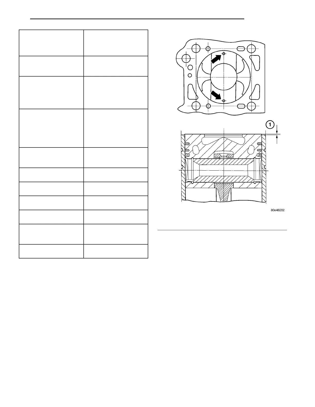
STANDARD PROCEDURE - MEASURING PIS-
TON PROTRUSION
After repla cing t he pistons/connecting rods or
machinin g the engine block con tact surface, it is th en
necessar y to measur e the piston prot rusion .
Measur e protr usion bet ween piston cr own and cyl-
inder hea d contact surface without the hea d ga sket
insta lled. Th e measur ment must be carried out in
the dir ection of the piston pin in order to elimin ate
piston rock.
(1) Measur e piston pr otrusion at the two measur-
ing point s (a rrows) (Fig. 39).
Piston protrusion with new cran kcase should be
0.38 - 0.62 m m .
REMOVAL
(1) Disconn ect the n egat ive battery cable.
(2) Remove the engine (Refer t o9-ENGINE-
REMOVAL).
(3) Remove the cylin der head (Refer to 9 -
ENGINE/CYLINDER HE AD - REMOVAL).
(4) Remove t he oil pan (Refer to 9 - ENGINE/LU-
BRICATION/OIL PAN - REMOVAL).
(5) Push back on the ch ain tensioner a nd remove
the oil pump chain from th e oil pu mp.
(6) Remove the oil pu mp.
NOTE: Mark the connecting rod and connecting rod
bearing cap to each other at the inlet side.
(7) Remove the connect ing rod bea ring cap.
NOTE: Do Not mix up the top and bottom connect-
ing rod bearing shells.
(8) Mark the connect ing rod bearing shell a nd th e
connect ing rod bea ring cap to each oth er.
Fig. 39 MEASURING PISTON PROTRUSION
1 - PISTON PROTRUSION MEASUREMENT
VA ENGINE 9 - 47